Last updated on June 8th, 2026 at 19:10
In this guide we will be taking a look through the deployment of the full VCF 9 suite, using the new easy installer
We will go through installing and configuring ESX for the management network and setting the certificates up, I will give a very rough overview of the networking, but this varies per vendor and wont be covered in great detail
Then, deploying the VCF installer appliance, which will build the foundation of the environment where we can continue with some day 2 deployment steps
So what is included with VCF 9
- SDDC Manager
- vCenter
- vSAN (1TiB/Core)
- NSX
- Identity Broker
- Real Time Metrics
- Supervisor/VKS/Tanzu
- VCF Operations (Aria)
- VCF Automation (Aria)
- Log Management (VCF/Aria Operations For Logs)
- VCF Operations For Networks (Aria)
- Private AI Service
The deployment of the private AI service isnt in this deployment guide as I dont have the GPUs/Nvidia vGPU licenses for it
We will want a minimum of two nodes running Fibre Channel or NFS storage, or three for vSAN. though I recommend four as a minimum for vSAN, in this guide we will be looking at vSAN for storage
iSCSI storage is supported but not as principle storage, only as supplemental so you will need one of the above types for some of the appliances, it can be made to work with a convergence, but this is not covered by this guide
Here is a bill of materials for everything we will be deploying for our management domain
The big draw back here is, while moving services into the new VCF Service Runtime makes a lot of things easier to scale and use, this dramatically increases the minimum requirements, which is a shame
- vCenter – 4vCPU 21GB
- 3x NSX Manager – 6vCPU 24GB
- 1x SDDC Manager – 4vCPU 16GB
- VCF Services Runtime – 42vCPU 82GB
- vSAN ~32GB in RAM Cache
- 2x Edge Nodes – 8vCPU 32GB
- 3x Control Plane Supervisor Nodes – 4vCPU 16GB
- VCF Operations – 4vCPU 16GB
- VCF Operations Collector – 4vCPU 16GB
- VCF Automation – 24vCPU 96GB
- Log Management – 8vCPU 16GB
- Real Time Metrics – 16vCPU 20GB
- VCF License Server – 2vCPU 4GB
- VCF Operations For Networks Controller – 8vCPU 32GB
- VCF Operations For Networks Collector – 4vCPU 12GB
You will want a minimum of four NICs per host, I recommend six which is what I am using, we will also want to consider the following
Physical Network
Here, they key takeaway, is all switch ports need to be the same, with an MTU of 9216, I recommend not using a LAG or port channel of any kind of logical NIC grouping, VLT/VSX/MC-LAG will still work
LAG support has been added, however I feel this is simpler from a networking configuration perspective
And example of the port configured on my switch, has the native VLAN on the default 1, though it is best practices to change this, eg 4092, I have the needed VLANs trunked, this included other VLANs VMs may need, and an MTU of 9216, here is what I have on my Dell OS10 switch
interface ethernet1/1/44
no shutdown
switchport mode trunk
switchport access vlan 1
switchport trunk allowed vlan 1023-1040
mtu 9216
flowcontrol receive on
- Top of Rack switches are configured. Each host and NIC in the management domain must have the same network configuration
- IP ranges, subnet mask, and a reliable L3 (default) gateway for each VLAN are provided
- Jumbo Frames (MTU 9000) are recommended on all VLANs. At a minimum, MTU of 1600 is required on the NSX Host Overlay VLAN and must be enabled end to end through your environment
- VLANs for management, vMotion, vSAN/NFS and NSX Host Overlay networks are created and tagged to all host ports. Each VLAN is 802.1q tagged
- Management IP is VLAN backed and configured on the host. vMotion & vSAN IP ranges are configured during the deployment process
Physical Hardware And ESX Hosts
- All servers are vSAN compliant and certified on the VMware Hardware Compatibility Guide, including but not limited to BIOS, HBA, SSD, HDD, etc
- Identical hardware (CPU, Memory, NICs, SSD/HDD, etc.) within the management cluster is highly recommended. Refer to vSAN documentation for minimal configuration
- Hardware and firmware (including HBA and BIOS) is configured for vSAN
- One physical NIC is configured and connected to the vSphere Standard switch. The second physical NIC is not configured
- Physical hardware health status is ‘healthy’ without any errors
- ESXi is freshly installed on each host. The ESXi version matches the build listed in the Cloud Foundation Bill of Materials
- All hosts are configured and in synchronization with a central time server (NTP). NTP service policy set to ‘Start and stop with host’
- Each ESXi host is running a non-expired license – initial evaluation license is accepted
Supporting Infrastructure
- All hosts are configured with a DNS server for name resolution. Management IP of hosts is registered and queryable as both a forward (hostname-to-IP), and reverse (IP-to-Hostname) entry
- Either the primary or secondary DNS servers should be hosted outside the VCF private cloud
For the different networks we will need a minimum of seven VLANs, I added my VLANs which are used over the guide, additional are required for workload domains
Management Domain
- Management – VLAN 1023
- vMotion – VLAN 1024
- vSAN – VLAN 1025
- NSX Host TEP – VLAN 1027
- NSX Edge TEP – VLAN 1028
- Edge Uplink 1 – VLAN 1029
- Edge Uplink 2 – VLAN 1030
Workload Domain
- ESX Management – VLAN 1031
- vMotion – VLAN1032
- vSAN – VLAN 1033
- NSX Host TEP – VLAN 1034
- NSX Edge TEP – VLAN 1035
- Edge Uplink 1 – VLAN 1036
- Edge Uplink 2 – VLAN 1037
Before we start we will need to get our DNS systems pre registered to avoid any conflicts during the VCF Installer, here is a full list of all my IP addresses for the management domain during the initial deployment and workload domain
Management Domain FQDN Table
| FQDN | IP Address | Purpose |
| lab-vcf91-sddc.leaha.co.uk | 10.1.23.109 | SSDC Manager |
| lab-vcf91-vcenter.leaha.co.uk | 10.1.23.110 | vCenter |
| lab-vcf91-esx01.leaha.co.uk | 10.1.23.111 | ESX Host 1 |
| lab-vcf91-esx02.leaha.co.uk | 10.1.23.112 | ESX Host 2 |
| lab-vcf91-esx03.leaha.co.uk | 10.1.23.113 | ESX Host 3 |
| lab-vcf91-esx04.leaha.co.uk | 10.1.23.114 | ESX Host 4 |
| lab-vcf91-vcfo.leaha.co.uk | 10.1.23.120 | VCF Operations |
| lab-vcf91-vcffs.leaha.co.uk | 10.1.23.127 | VCF Fleet Services FQDN |
| lab-vcf91-vcfoc.leaha.co.uk | 10.1.23.128 | VCF Operations Collector |
| lab-vcf91-vcfa.leaha.co.uk | 10.1.23.140 | VCF Automation |
| lab-vcf91-vcfasr.leaha.co.uk | 10.1.23.174 | VCF Automation Service Runtime |
| 10.1.23.240-245 | VCF Automation Node IPs | |
| lab-vcf91-nsx.leaha.co.uk | 10.1.23.160 | NSX VIP |
| lab-vcf91-nsx01.leaha.co.uk | 10.1.23.161 | NSX Node 1 |
| lab-vcf91-nsx02.leaha.co.uk | 10.1.23.162 | NSX Node 2 |
| lab-vcf91-nsx03.leaha.co.uk | 10.1.23.163 | NSX Node 3 |
| lab-vcf91-vcflogmgmt.leaha.co.uk | 10.1.23.130 | Log Management |
| lab-vcf91-vcfon.leaha.co.uk | 10.1.23.150 | VCF Operations For Networks Platform |
| lab-vcf91-vcfonc.leaha.co.uk | 10.1.23.156 | VCF Operations For Networks Collector |
| lab-vcf91-edge01.leaha.co.uk | 10.1.23.166 | NSX Edge 1 |
| lab-vcf91-edge02.leaha.co.uk | 10.1.23.167 | NSX Edge 2 |
| lab-vcf91.vcfols.leaha.co.uk | 10.1.23.170 | VCF License Server |
| lab-vcf91-vcfis.leaha.co.uk | 10.1.23.171 | VCF Instance Services FQDN |
| lab-vcf91-vcfib.leaha.co.uk | 10.1.23.172 | Identity Broker |
| lab-vcf91-vcfsr.leaha.co.uk | 10.1.23.173 | VCF Service Runtime FQDN |
| 10.1.23.200-230 | VCF Service Rumtime IP Pool | |
| 10.1.23.50-54 | Supervisor Control Plane Management |
Workload Domain FQDN Table
| FQDN | IP Address | Purpose |
| lab-vcf91-wld-vcenter.leaha.co.uk | 10.1.23.180 | vCenter |
| lab-vcf91-wld-esx01.leaha.co.uk | 10.1.31.111 | ESX Host 1 |
| lab-vcf91-wld-esx02.leaha.co.uk | 10.1.31.112 | ESX Host 2 |
| lab-vcf91-wld-esx03.leaha.co.uk | 10.1.31.113 | ESX Host 3 |
| lab-vcf91-wld-esx04.leaha.co.uk | 10.1.31.114 | ESX Host 4 |
| lab-vcf91-wld-esx05.leaha.co.uk | 10.1.31.115 | ESX Host 5 |
| lab-vcf91-wld-esx06.leaha.co.uk | 10.1.31.116 | ESX Host 6 |
| lab-vcf91-wld-esx07.leaha.co.uk | 10.1.31.117 | ESX Host 7 |
| lab-vcf91-wld-esx08.leaha.co.uk | 10.1.31.118 | ESX Host 8 |
| lab-vcf91-wld-esx09.leaha.co.uk | 10.1.31.119 | ESX Host 9 |
| lab-vcf91-wld-vcfoc.leaha.co.uk | 10.1.23.129 | VCF Operations Collector |
| lab-vcf91-wld-edge01.leaha.co.uk | 10.1.31.131 | Edge 1 |
| lab-vcf91-wld-edge02.leaha.co.uk | 10.1.31.132 | Edge 2 |
I also find that understanding how things flow and are set out in a diagram helps, this is a topology diagram of what we will be deploying, bare in mind VCF 9 topology is not set in stone, for example, the first domain is called the management domain, but you can use it for management and workloads if you want
One of the nice changes that we can see from this diagram, is the first workload domain no longer requires a dedicated NSX instance and can be attached to the management domain’s NSX instance, this should reduce the overhead where shared NSX instances are fine
1 – ESX
1.1 – Installation
Mount this to the server, by using rufus to create a bootable USB, or by mounting it to your servers virtual CD ROM in the IPMI, iDRAC for Dell and iLO for HPE
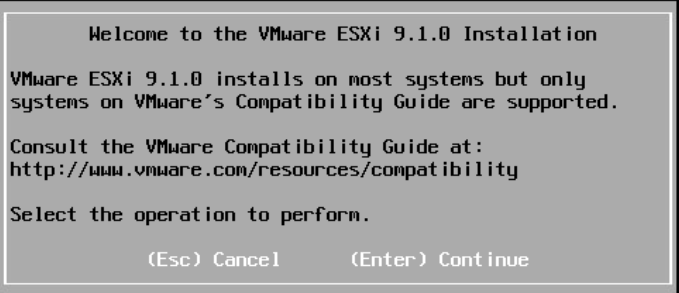
Once the server has booted ESX, you’ll have this screen, select enter to continue
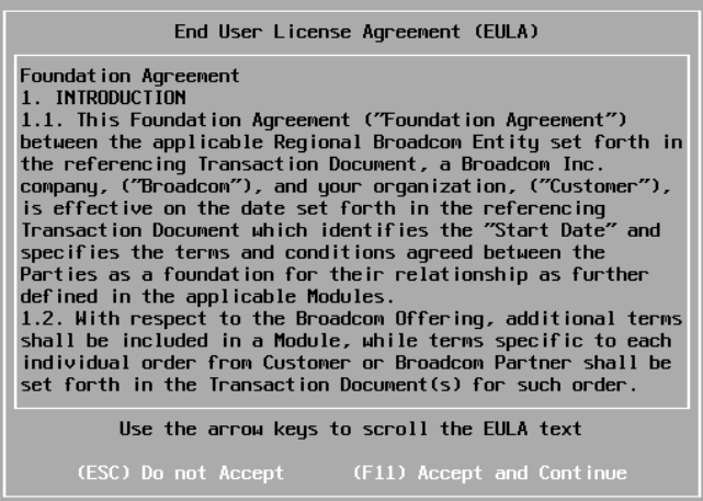
Accept the EULA with F11
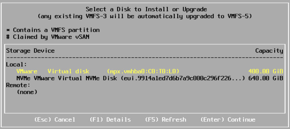
It will then scan for bootable devices, for a production system this should be something in RAID 1
Examples are Dell’s BOSS card
For HPE G11 you should have the NS204i-U, or for G10 systems the NS204i-P, which is a PCIe card
As this is a lab, I have a virtual disk, and will be using the 400GB one by making sure its highlighted in Yellow and clicking Enter to Continue
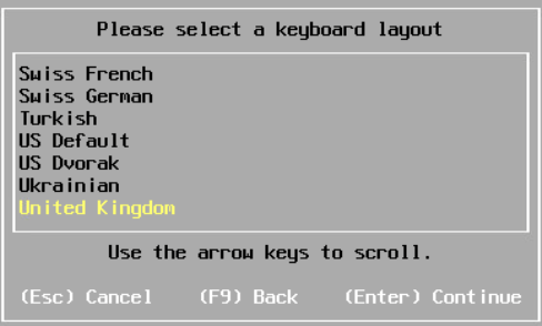
Select your keyboard layout and hit Enter
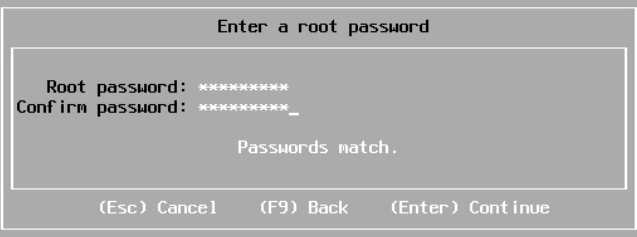
Set a root password, use something easy to use, we can set a secure random one later
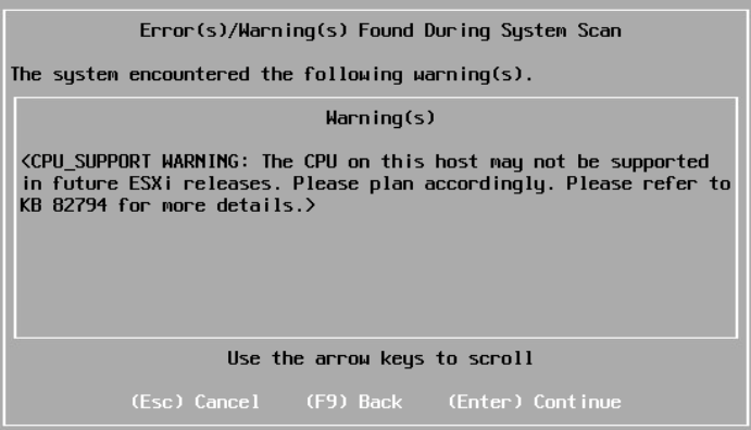
You may get a CPU warning depending on your hardware
Press Enter
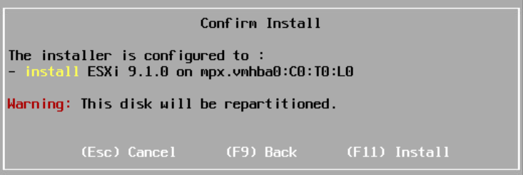
Then click F11 to install
Once thats done, reboot the server when prompted and unmount your media
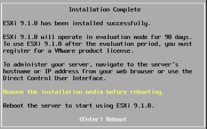
Once thats done, reboot the server when prompted and unmount your media

1.2 – Configuring ESX
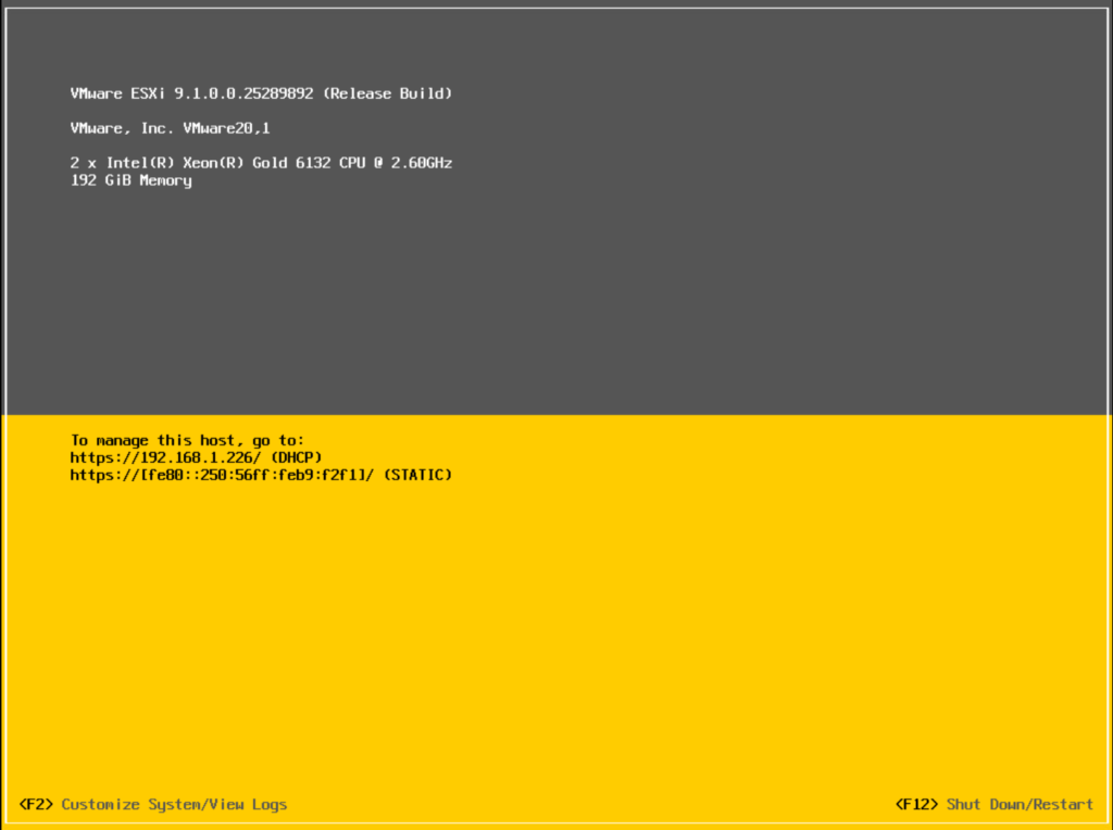
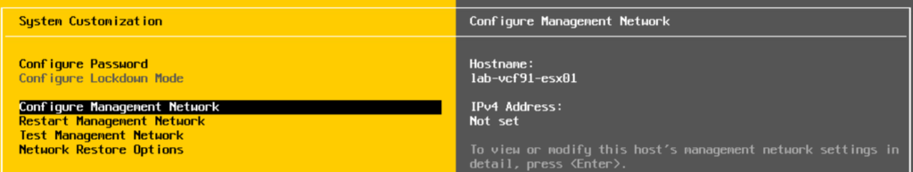
When the host boots, it should look like this, press F2 to login
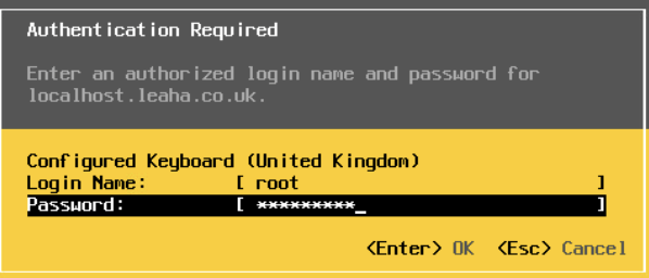
Enter the root credentials and press enter
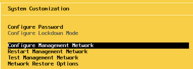
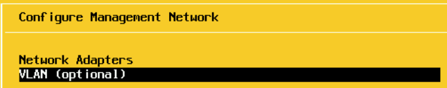
Scroll to Configure Management Network and press enter
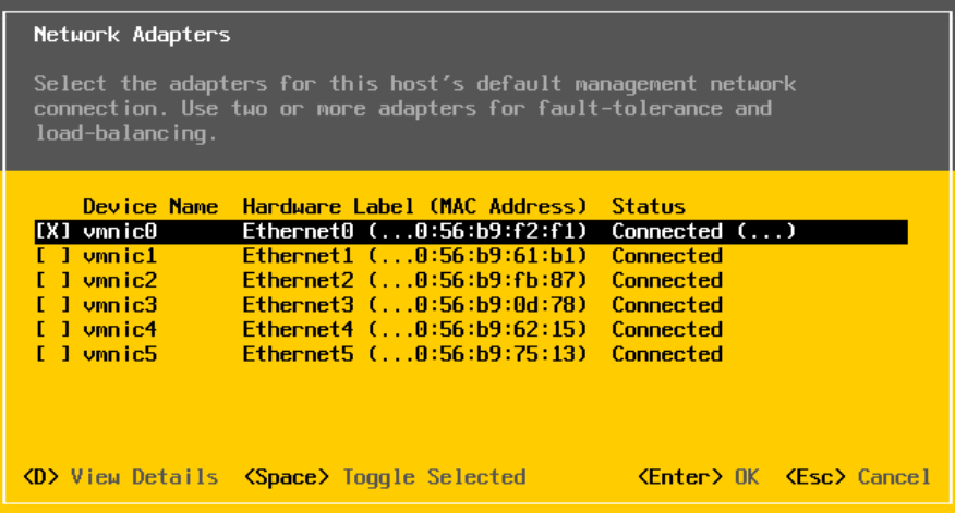
Press Enter on Network Adapters and ensure that a connected Nic is selected, these should all be configured the same on the switch
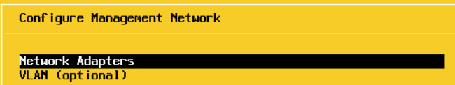
In my case VMNIC0 is connected, and I will be using this for management, so I will press Escape and leave it as it is
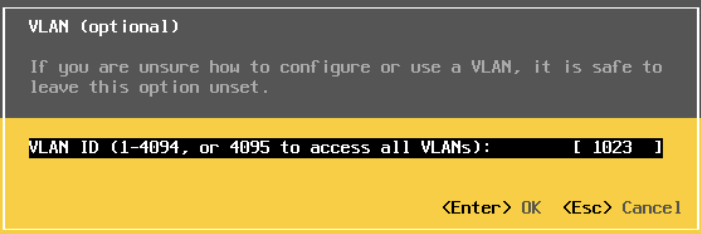
Press enter on VLAN
And enter your ESXi management VLAN, I am using VLAN 1023
This is only needed if you have your VLANs trunked down, if your management VLAN is the native VLAN you can ignore this, as all my VLANs are trunked down, I am entering mine
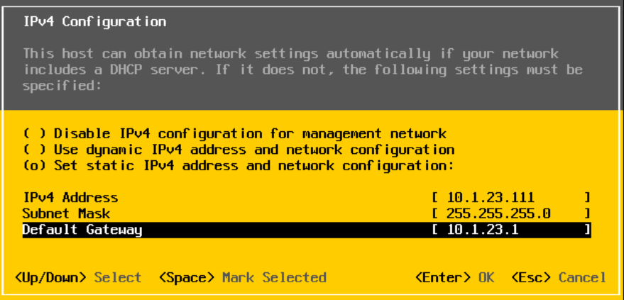
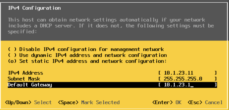
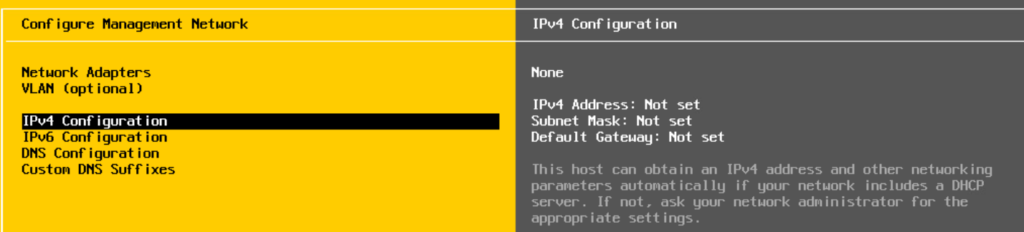
On IPv4
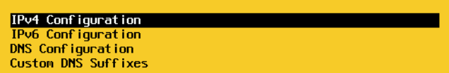
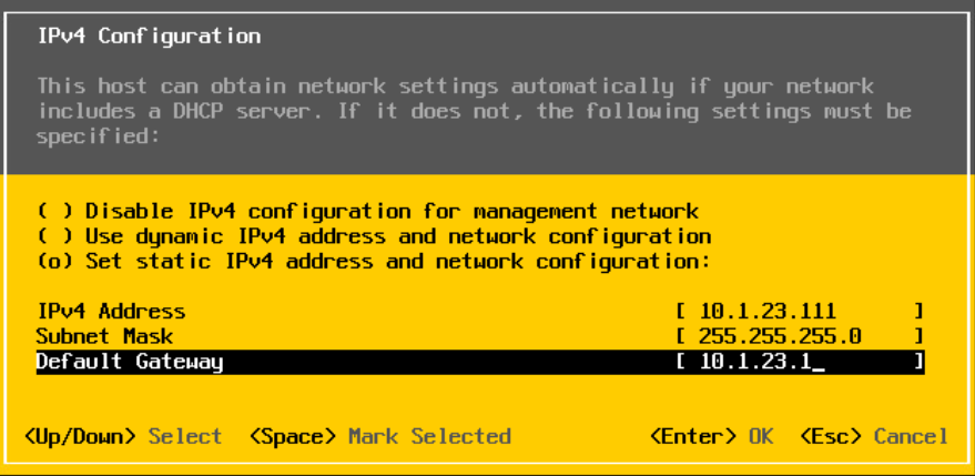
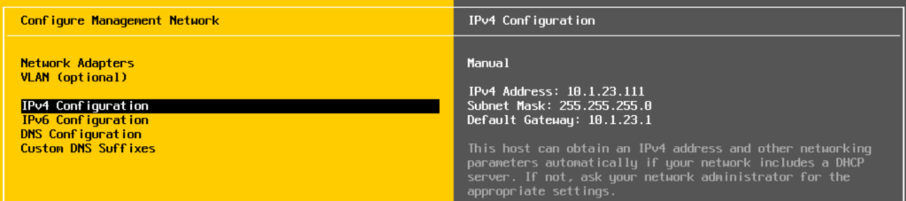
Use the space bar to select the third option to set a static IP and add your management IP details in and press enter to Save
For IPv6, select disable on the first option, unless you are specifically using it, and press Enter
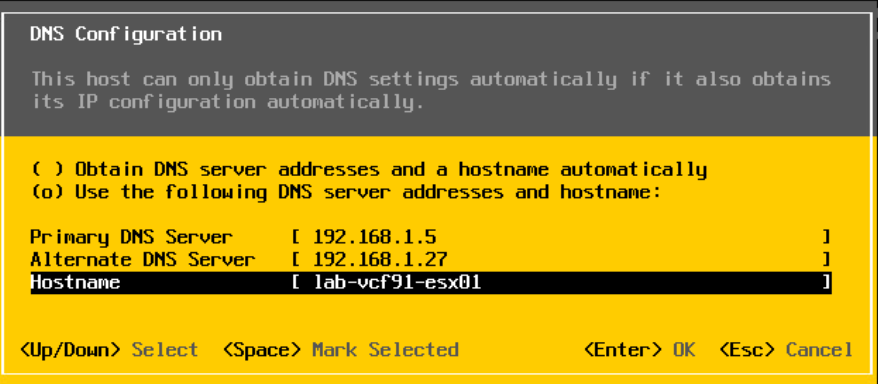
Add your DNS servers and the hostname for this server and press Enter
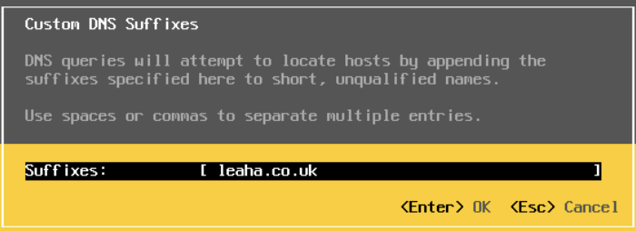
Add your domain under DNS Suffixes and press Enter
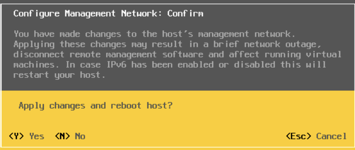
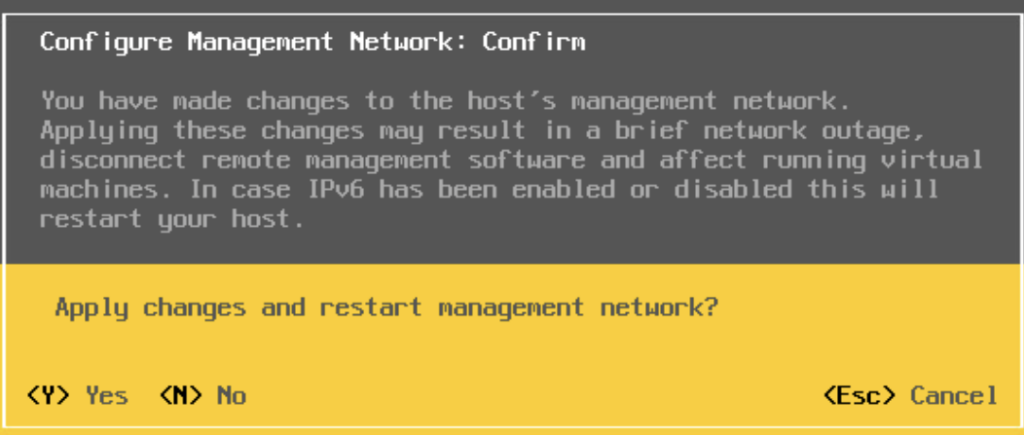
Now press Escape and enter Y to apply changes and reboot the host
Then, login on the WebUI at
https://fqdn
And login with the root credentials
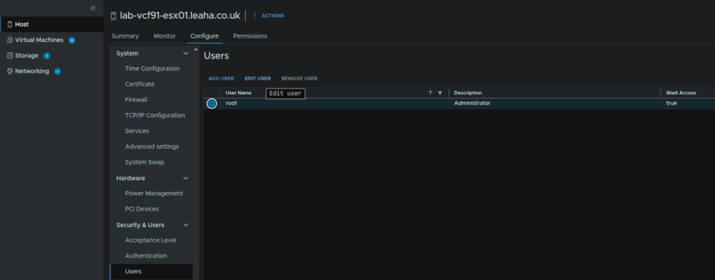
Navigate to Host/Configure/Security & Users/Users, and click the root account and click Edit User to change the root password to something more secure
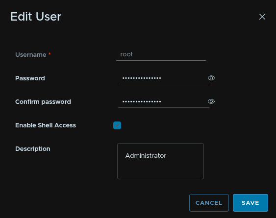
Then add the password
This needs to be 15 characters with the only allowed special characters being !@#$%^&*
Then click Save
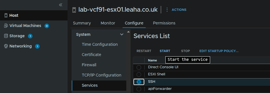
Then we need to enable SSH, click Host/Configure/System/Services select SSH and click Start
Now we need to SSH into the host with the root credentials, using something like Putty and run the following to set the hostname/FQDN correctly for the certificate and renew it for the VCF deployment wizard
For my host, lab-vcf91-esx01, lets set the hostname with
esxcli system hostname set -H=<hostname>
So for my host this is
esxcli system hostname set -H=lab-vcf91-esx01Then set the FQDN with
esxcli system hostname set -f=<fqdn>Which for my host is
esxcli system hostname set -f=lab-vcf91-esx01.leaha.co.ukNow renew the certificates with
/sbin/generate-certificatesAnd reboot the host with
rebootWhen it comes back up, you will need to restart SSH for the cloud builder
Lastly, we need to setup NTP on all servers, you can use a windows App, DC or a docker container, for this
Head to Host/Comfigure/System/Time Configuration and click Edit under Network Time Protocol
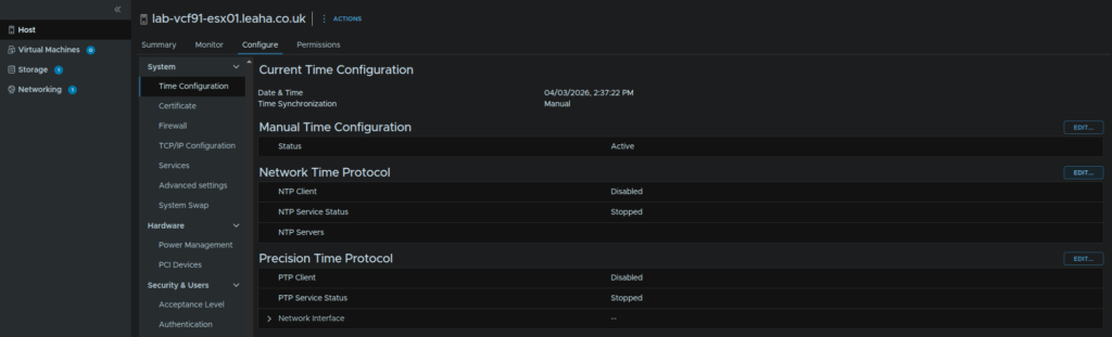
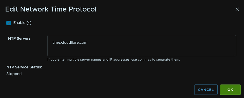
Check the box to enable it, enter your NTP server and click ok
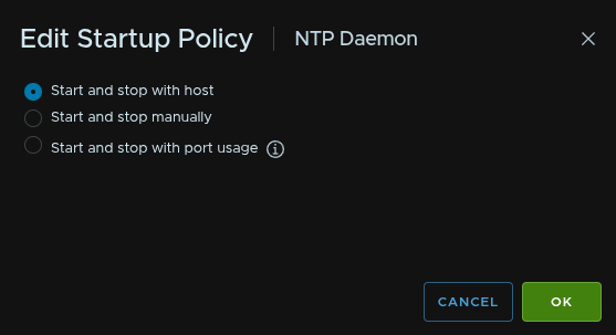
Then, under services, click NTP Daemon and click Edit Startup Policy
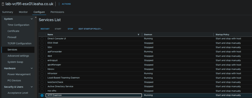
Check the radio button for Start And Stop With Host and click ok
We will need to repeat this on the remaining hosts
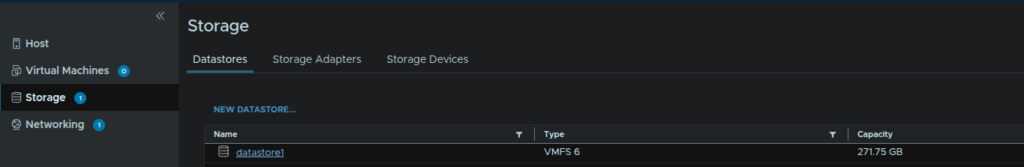
Before we proceed we need to check we have enough space on the first host to deploy the VCF installer appliance, your boot device will typically be 512GB or larger so there should be a good size local datastore created we can use for this as we cant use our vSAN disks
We can check this under Storage/Datastores
Mine is only 271GB but should be enough
1.3 – Virtual Host Management NIC Prep
This only seems to happen for virtual ESX hosts used in labs, when the build option tries to migrate the management vmk to a VDS it will fail
This does not need to be done on physical hardware
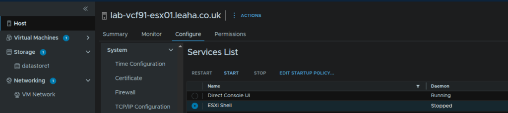
We need SSH and the ESX Shell, to enable this, click Host/Configure/System/Services, select ESXi Shell and click Start
Then open up the ESX console and press Alt + F1 to access the shell and login
Then run
esxcli network ip interface list | lessWe should see vmk0, the management interface
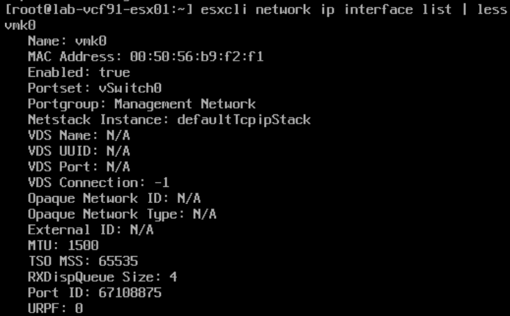
We need to note the portgroup, which should be ‘Management Network’
We can press ‘q’ to exit this
Now remove the interface with
esxcli network ip interface remove –-interface-name=vmk0Then recreate it with
esxcli network ip interface add -–interface-name=vmk0 -p "Management Network"We can press Alt + F2 to switch back to the DCUI, press F2 and login as root
Press Enter on Configure Management Network
Press Enter on IPv4 Configuration
Use the third option to set a static IP and enter the details setup at the ESX deployment stage and press Enter
Then press Escape
And press Y here
Now back in the host UI, click Host/Configure/System/Services, select ESXi Shell and click Disable

Then repeat for the remaining hosts
2 – VCF Installer
2.1 – Deploying The Appliance
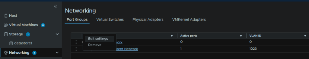
Log into the first host and click Networking
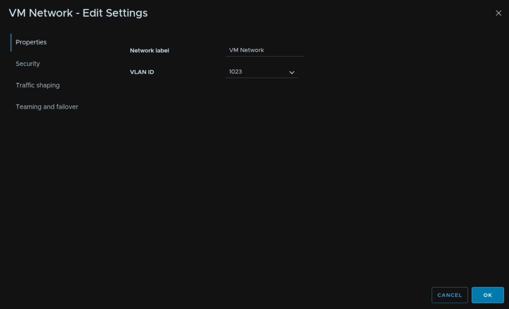
If you set a VLAN for the management VLAN and the management components are going on the same VLAN, which I recommend, we will need to edit the VM Network to set this VLAN, click Networking, then click the three dots on the VM Network entry and click Edit Settings
Set the VLAN tag and click ok
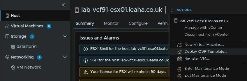
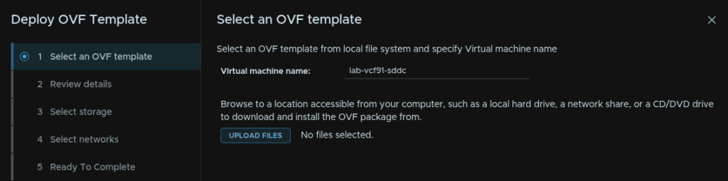
Now click Host/Actions/Deploy OVF Template
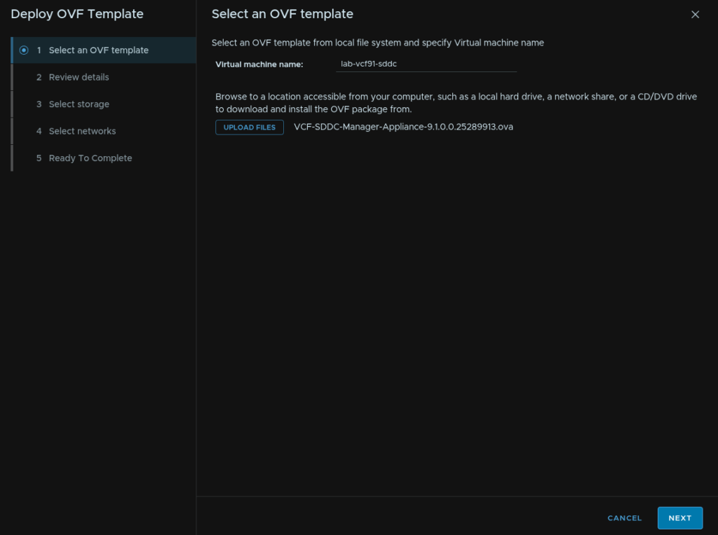
Give the VM a name and click Upload Files
Double click the SDDC Manager OVA

Then click Next
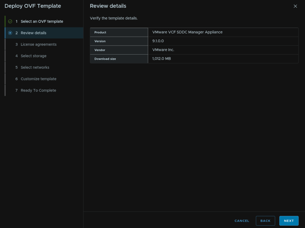
Click Next
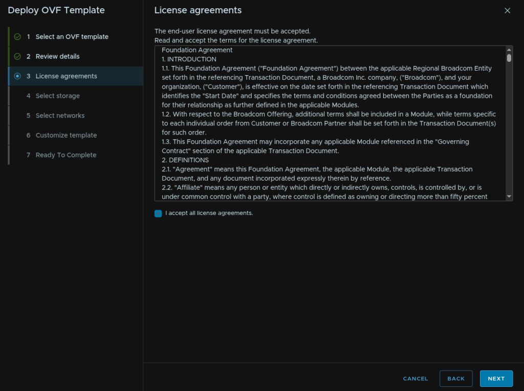
Accept the EULA
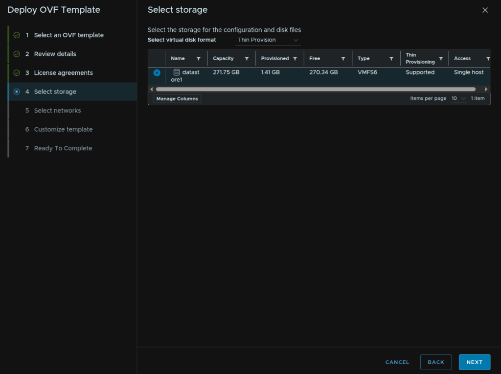
Select the default datastore and make sure Thin Provision is enabled then click Next
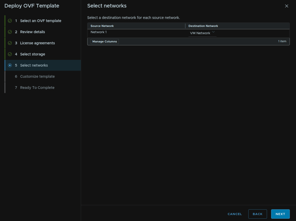
Make sure the VM Network is selected and click Next
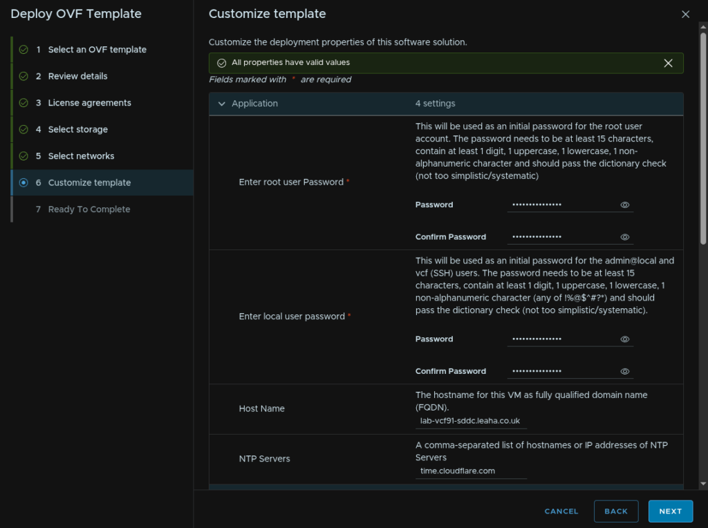
Under Application enter a root and local user password, these need to be 15 characters with the only special characters being !@#$%^&*
For the hostname enter the FQDN and for NTP add your NTP server
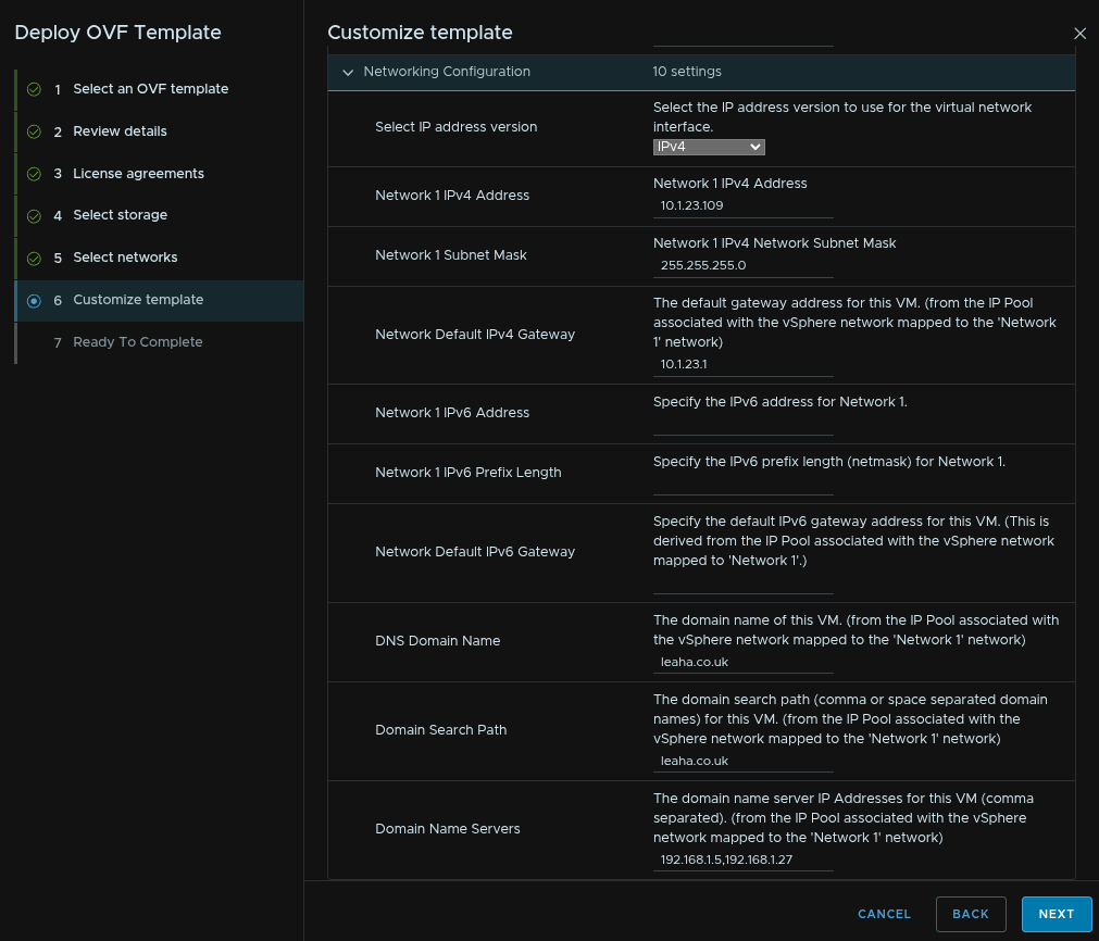
For the networking section, select the IP version, likely IPv4, enter the SDDC Manager IP address, subnet mask, gateway, DNS domain and search domain path and DNS servers, comma separated, then click Next
And click Finish
Do not refresh your page while this is deploying
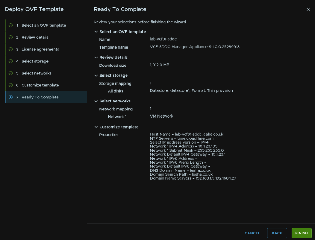
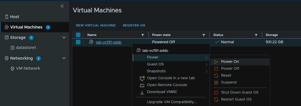
When thats uploaded, click Virtual Machines, right click the VM and click Power/Power On
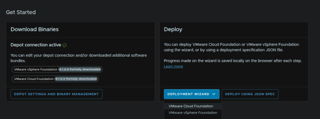
2.2 – Downloading Binaries
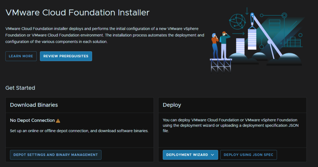
Now we have the appliance deployed we need to download all the software binaries, log into the VCF Installer on
https://fqdn
Then click Depot Settings And Binary Management
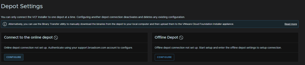
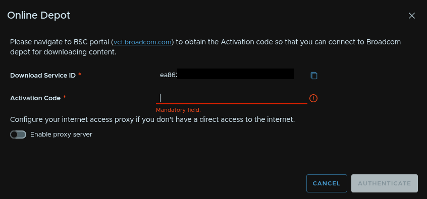
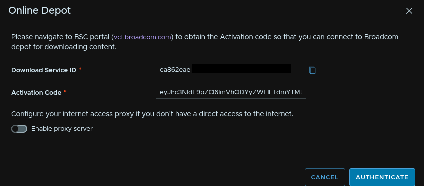
On the Connect To The Online Depot widget, click Configure
Copy the service ID and then head to vcf.broadcom.com
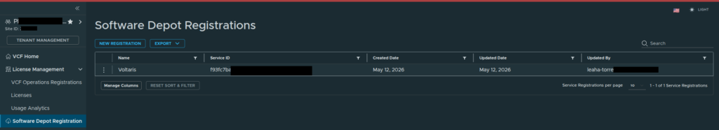
Then click Software Depot Registration and click New Registration
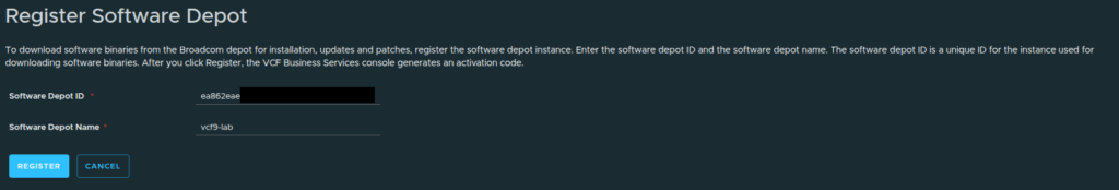
Paste the Service ID from the VCF Installer and give the depot a name, then click Register
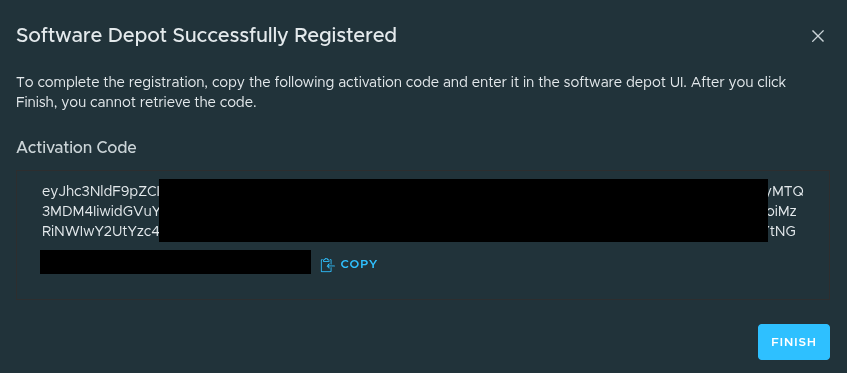
Copy the activation code and click Finish
Paste this into the Activation Code section in the VCF Installer and click Authenticate
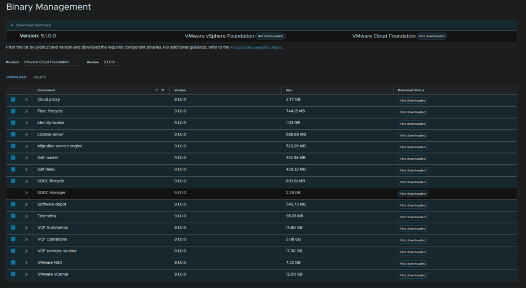
At the bottom, select your release version, I am doing 9.1.0.0, and select everything apart from the SDDC Manager and click Download
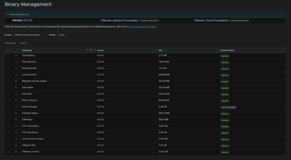
When its all done, it should look like this
We can then click Return Home at the top left to get back to the main menu
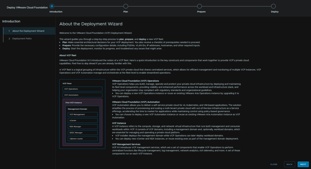
2.3 – Introduction
As we proceed through we will need to add various appliances, ensure all are DNS registered as you go through it before you finish the deployment
On the Deploy Widget, click Deployment Wizard/VMware Cloud Foundatio
Click Next
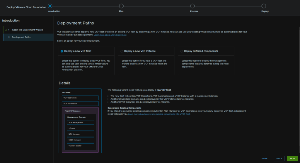
As this is a brand new deployment from scratch we want to make sure we have Deploy A New VCF Fleet selected and click Next
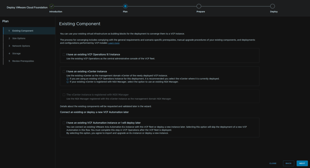
2.4 – Plan
2.4.1 – Existing Components
We dont have any components, so we can uncheck anything, we will be deploying VCF Automation, but it can be skipped by checking the bottom box, when you are happy click Next
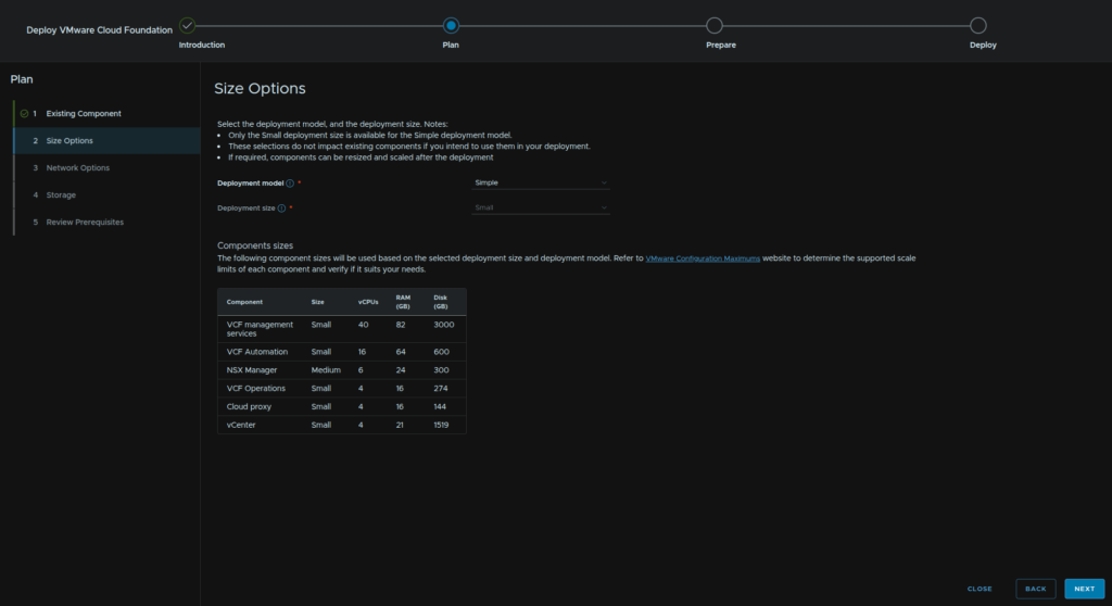
2.4.2 – Size Options
We can choose HA if its needed, this will significantly increase the deployment requirements
Sadly, if you opt for simple, you are stuck with small, for example, you may want to configure a Large NSX cluster as workload domains can now be added to the management domain NSX instance, but most things can be scaled as a day 2 activity, though I cant see a way to resize NSX, however you can possibly shut the managers down and manually resize them
HA requirements – minimum
| Component | vCPU | RAM – GB | Disk – GB |
| VCF Management Services | 84 | 174 | 3600 |
| VCF Automation | 72 | 288 | 2700 |
| NSX Manager | 18 | 72 | 900 |
| VCF Operations | 24 | 96 | 822 |
| Cloud Proxy | 8 | 48 | 144 |
| vCenter | 8 | 30 | 1658 |
Simple requirements – fixed
| Component | vCPU | RAM – GB | Disk – GB |
| VCF Management Services | 40 | 82 | 3000 |
| VCF Automation | 24 | 96 | 600 |
| NSX Manager | 6 | 24 | 300 |
| VCF Operations | 4 | 16 | 274 |
| Cloud Proxy | 4 | 16 | 144 |
| vCenter | 4 | 21 | 1519 |
For this guide we will be doing with a simple config, you can always scale out as needed later down the line, small will be the fixed Deployment Size, click Next
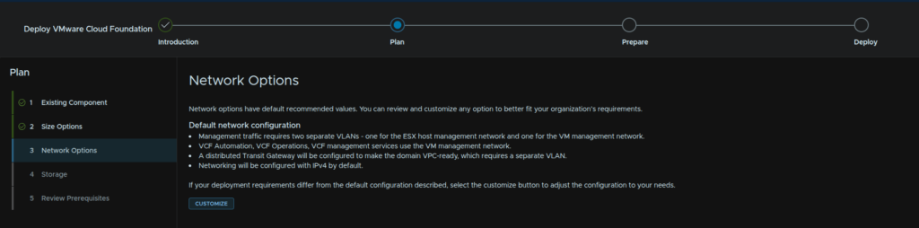
2.4.3 – Network Options
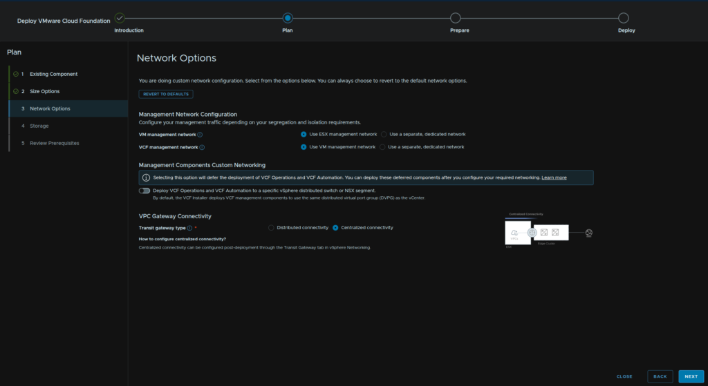
Click Customize
For a smaller environment, a we dont really need to split VM and VCF management up, so select Use ESX Management Network, you can provide a separate network if you like though, but using the same keeps the deployment simpler
Leave Management Components Custom Networking off, this will mean Ops and Automation are on the same L2 network as vCenter
For VPC Gateway Connectivity we will want Centralized Connectivity, only use Distributed Connectivity if you know you need it
Then click Next
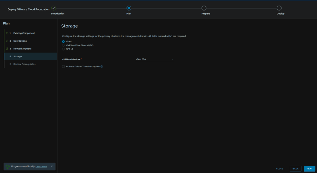
2.4.4 – Storage
Select our storage type, we can use vSAN, VMFS over FC or NFS v3, we will be using vSAN, and the architecture will be ESA, then click Next
2.4.5 – Review
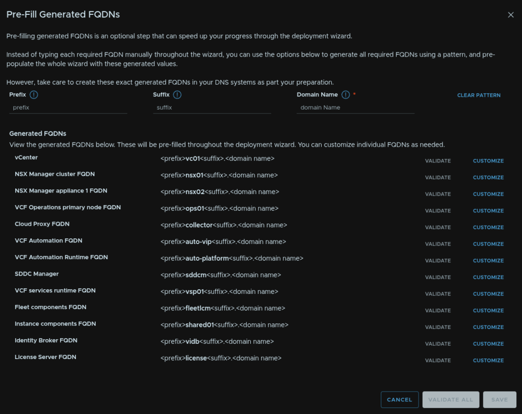
We can then see the resource requirement, for the minimum, VLAN requirement, which is four, and FQDNs, we have a table at the start where we planned this out and I wilkl be manually entering them, but you can click the Pre-Fill Generated FQDNs In Wizard and setup a pattern if you wanted
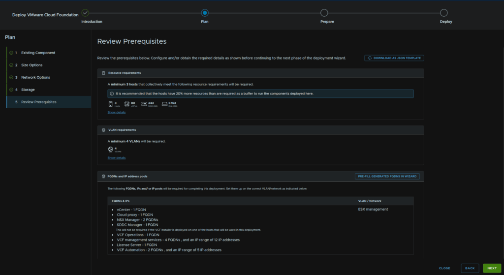
The form for the pattern is this
If, like me, you didnt fill this in, you can manually enter them during the next stage
When you are happy click Next
2.5 – Prepare
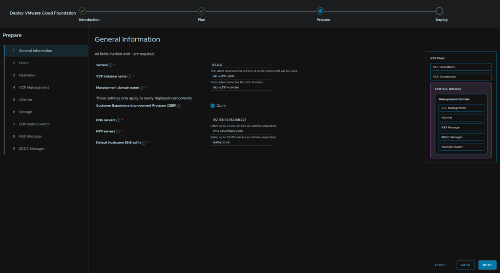
2.5.1 – General Information
Select the version, which wants to be 9.1.0.0 in this case, enter a VCF Instance name, as this is the SDDC Manager, I will use the same name it has, and for the management domain, as thats based off the initial vCenter, I used thats hostname, opt in or out of the CIEP, and add your DNS and NTP servers, then DNS suffix, this should be automatically populated though
Then click Next
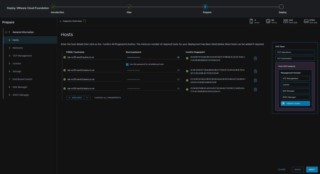
2.5.2 – Hosts
Enter our host FQDNs, I used the Add Host button so I have room for my 4th host, fill in their FQDNs and root passwords, you can use the check box beneath the first hosts password field to use that password for all hosts
Then click Confirm All Fingerprints
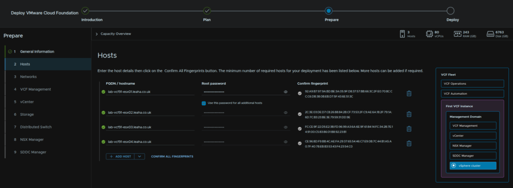
When thats done, click Next
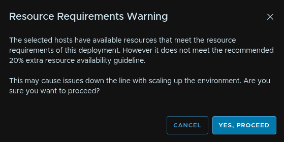
Click Yes, Proceed if you see this, mine will be flagging on vCPU/Storage, which will be fine in my lab
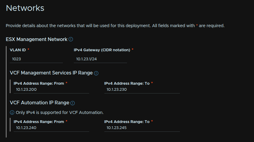
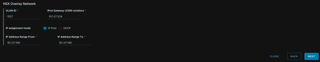
2.5.3 – Networks
Now we need our networks
For ESX add in the VLAN the ESX Management is on and its gateway in CIDR notation
As VCF Management Services and automation are already set to use the same network, they fall under here, we need 12 for a minimum deployment, but as it scales out to needing 30, I would allocate 30 here so its available if you ever need it
VCF Automation needs a total of 5 IP addresses set out for it
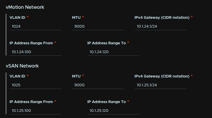
vMotion and storage, in my case vSAN, need enough IPs for each host, I added a wider range in case I want to add more hosts down the line
They also need the VLAN ID, MTU, which should be 9000, though ensure your physical switches have a slightly higher MTU, and their gateway in CIDR notation
For the NSX host TEP pool this will need its own VLAN, here enter the ID, gateway in CIDR notation, then an IP pool, double the range of the vMotion and vSAN IPs is needed here as each host will have 2 IPs, and make sure its set to IP pool not DHCP
Then click Next
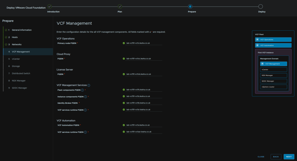
2.5.4 – VCF Management
We then need FQDNs for
- VCF Operations
- VCF Operations Cloud Proxy
- VCF Operations License Server
- VCF Fleet Services
- VCF Instance Services
- VCF Identify Broker
- VCF Services Runtime
- VCF Automation
- VCF Automation Services Runtime
When everything filled out and checked in DNS click Next
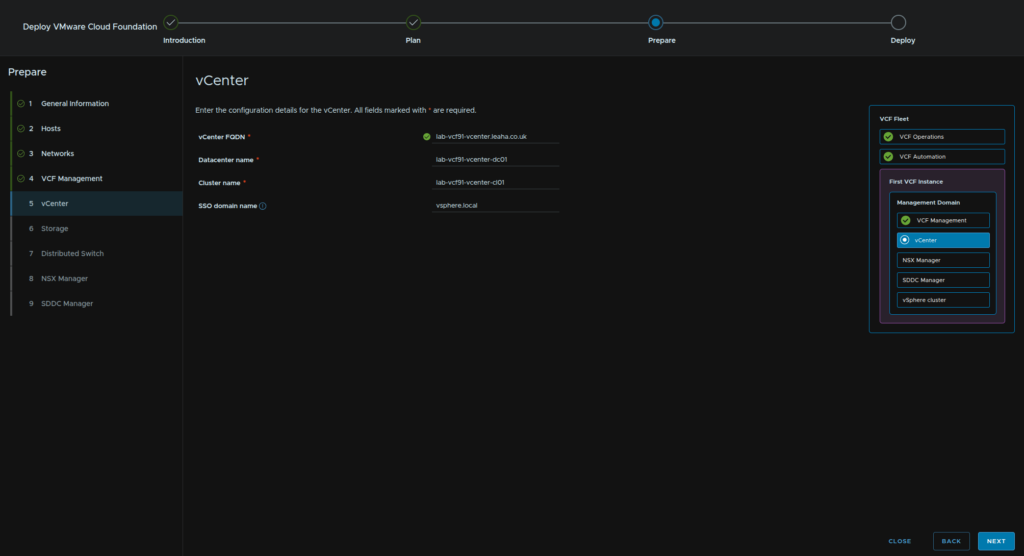
2.5.5 – vCenter
Enter the vCenter FQDN, Datacenter Name, Cluster Name and SSO domain, the default vsphere.local will be fine, then click Next
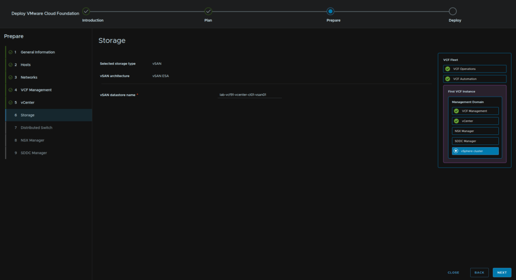
2.5.6 – Storage
Enter the vSAN Datastore Name, then click Next
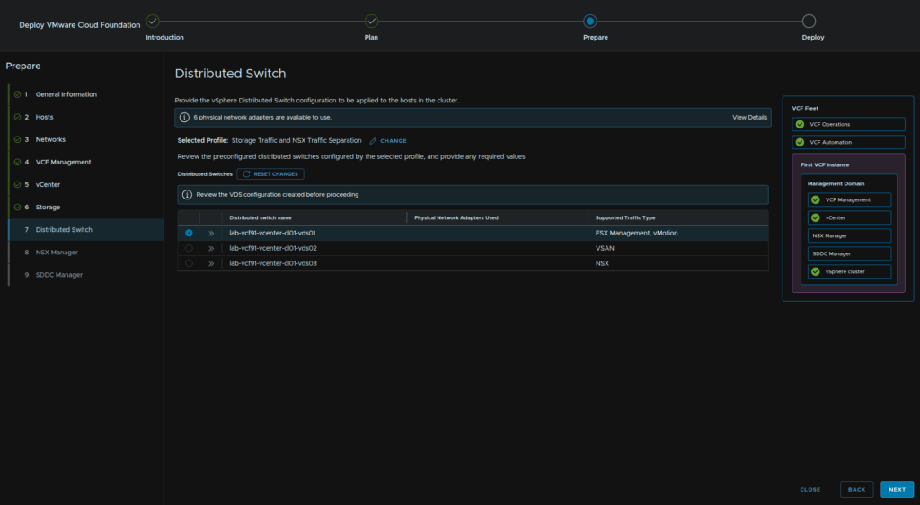
2.5.7 – Distributed Switch
For our networking topology, what we select depends on the number of NICs, I have 6, and I would recommend this many, but 4 also works, I would say 2 is below the minimum
If you have 4 NICs, click Select on Storage Traffic Separation
If you have 6 like me, click Select on Storage Traffic And NSX Traffic Separation
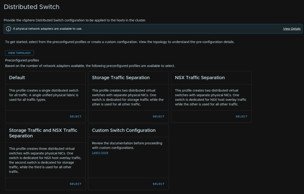
We can expand the VDS configuration, but unless you want to change the name, the default is fine, so click Next
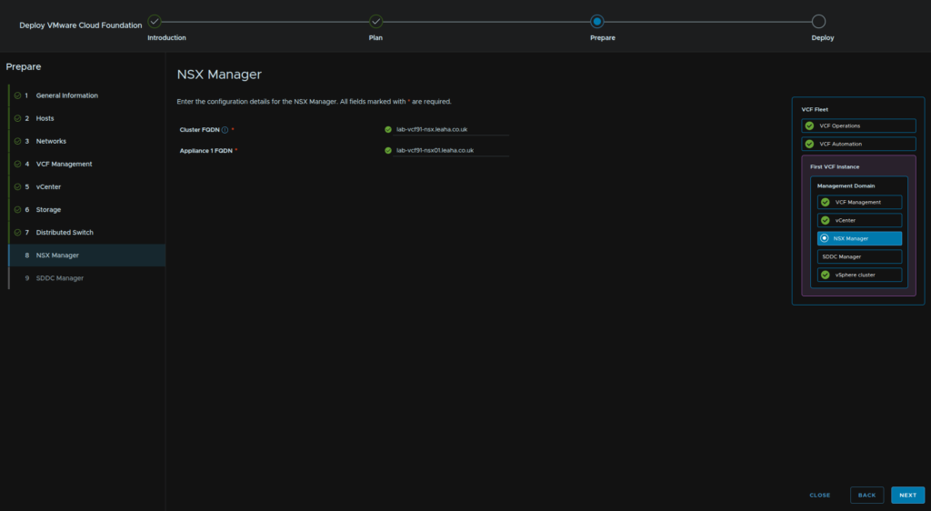
2.5.8 – NSX Manager
Enter the FQDN for the NSX VIP and manager then click Next
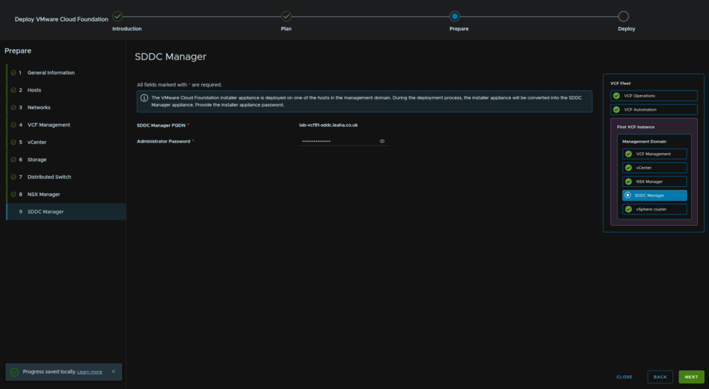
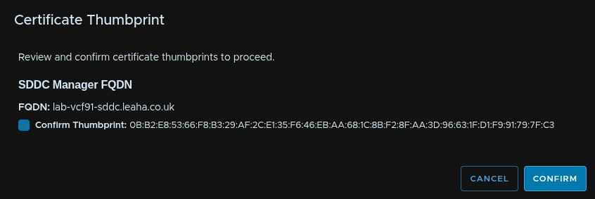
2.5.9 – SDDC Manager
Enter the admin@local password for the VCF Installer and click Next
Click Confirm for the thumbprint
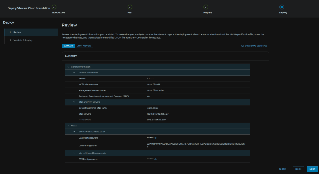
2.6 – Deploy
Review the config and click Next when you are happy
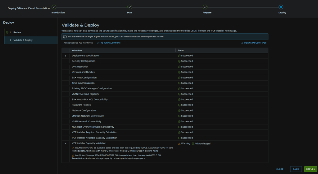
This will kick off the validation
If anything fails it must be addressed, the only warning I got was over capacity, it assumes a 1:1 ratio on pCPU to vCPU which is a little overkill, but you are unlikely to hit this in production and my storage is a little lower, with thin provisioning it should be fine, but ensure you have enough storage on a production system
When you are happy, click Deploy
We can then watch it go through all of the stages
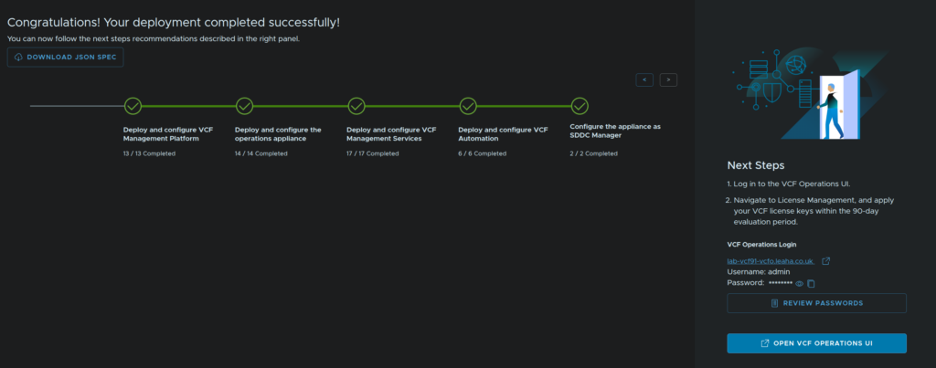
We can also click Review Passwords for all the generated credentials, ensure you save these
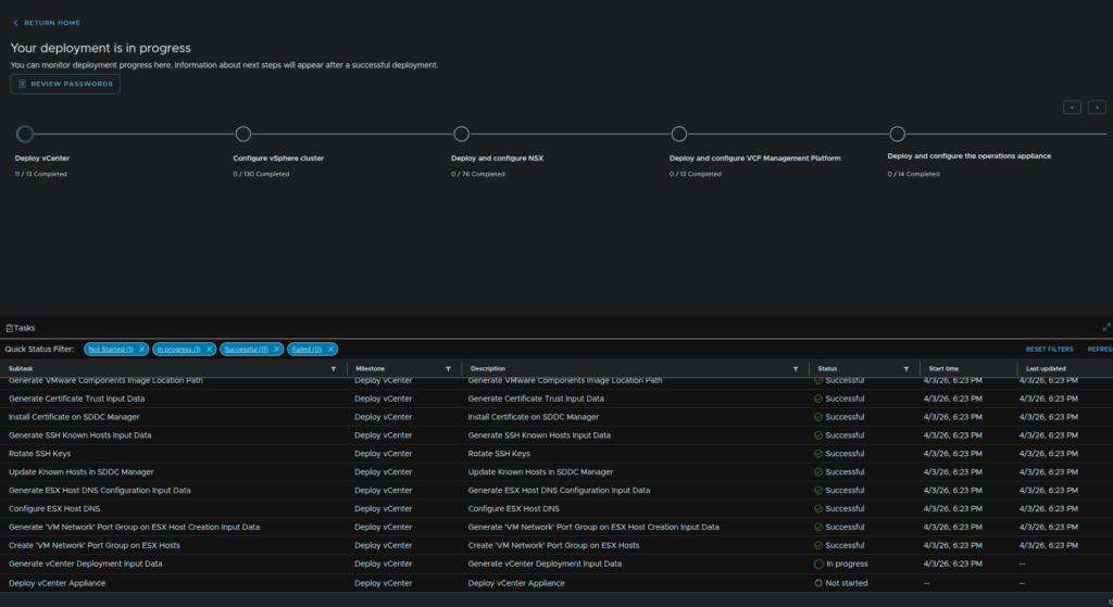
You can copy this as a JSON or CSV
When its done it will look like this and we can proceed to the VCF Operations UI
3 – NSX
3.1 – Expanding The NSX Management Cluster
The one system we really do want HA on is the NSX manager cluster, we need to expand this with the SDDC Manager API, as of 9.0.x
Thankfully we dont need to do anything complex with this, as APIs can be very confusing if you are new, Operations has an API explorer with a nice template we can use to easily do this
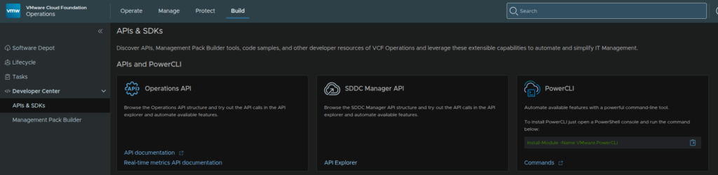
Log into VCF Operations and click Build/Developer Center/APIs & SDKs then click API Explorer on the SDDC Manager API widget
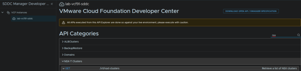
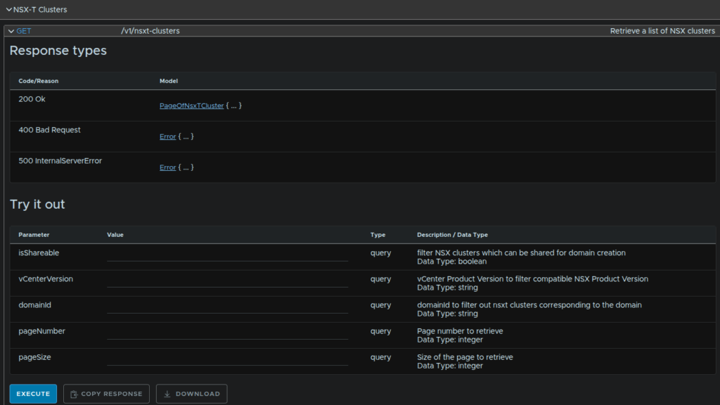
Search for NSX and the bit we want to expand is the GET request for getting our clusters, this will give us our cluster ID which we need for the scale out operation
Expand the request and click Execute, you dont need to fill anything out
We can see the cluster object, you can click the link to expand it
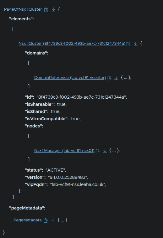
Now we can see our single node, and we have the ID we can copy for later
In my case my ID is 8f4739c3-f002-493b-ae7c-731c1247344a
Now we need the POST request to scale out the cluster

We have two main parameters we need, the cluster ID and the body, for the cluster ID, enter your ID
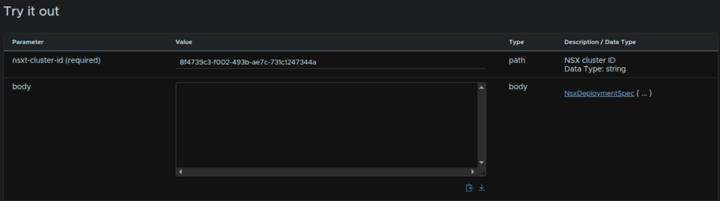
We then need to add the body, the template for it is this
Remove the IPv6 entries, like mine below, if you arent using it
{
"nsxManagerSpecs": [
{
"name": "",
"networkDetailsSpec": {
"dnsName": "",
"gateway": "",
"ipAddress": "",
"ipv6Gateway": "",
"ipv6PrefixLength": 0,
"subnetMask": ""
}
},
{
"name": "",
"networkDetailsSpec": {
"dnsName": "",
"gateway": "",
"ipAddress": "",
"ipv6Gateway": "",
"ipv6PrefixLength": 0,
"subnetMask": ""
}
}
]
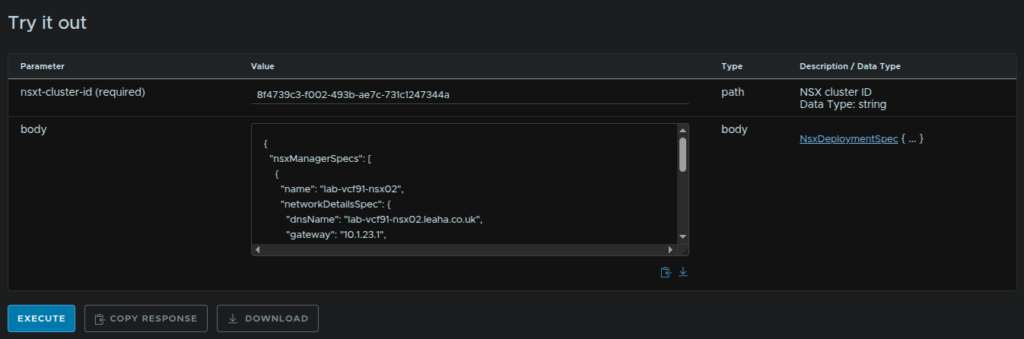
}We then need to fill our the variables like below, for each manager
- name – Hostname
- dnsName – FQDN
- ipAddress – IPv4 Addres
- gateway – Network Gateway
- subnetMask – Subnet Mask
This is what I did for my managers
{
  "nsxManagerSpecs": [
    {
      "name": "lab-vcf91-nsx02",
      "networkDetailsSpec": {
        "dnsName": "lab-vcf91-nsx02.leaha.co.uk",
        "gateway": "10.1.23.1",
        "ipAddress": "10.1.23.162",
        "subnetMask": "255.255.255.0"
      }
    },
    {
      "name": "lab-vcf91-nsx03",
      "networkDetailsSpec": {
        "dnsName": "lab-vcf91-nsx03.leaha.co.uk",
        "gateway": "10.1.23.1",
        "ipAddress": "10.1.23.163",
        "subnetMask": "255.255.255.0"
      }
    }
  ]
}
Then click Execute
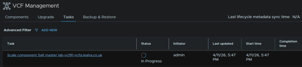
We’ll see it showing as in progress now
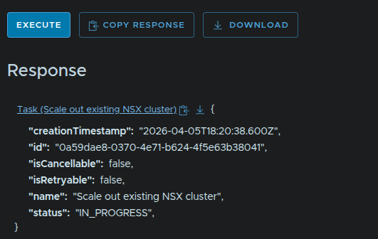
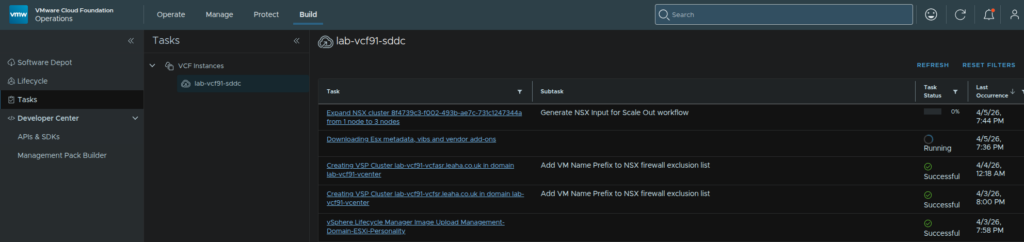
We can view the status from Build/Tasks and then by clicking our VCF instance
3.2 – Setting Up NSX Networking
Now we have the extra appliances deployed we need some Edge VMs to do the network transport
We need two DNS registered FQDNs for this
Its here that we need our Uplink VLANs for BGP
I would recommend having ToR 1 owning Uplink 1 as the BGP neighbor on this subnet, and ToR 2 owning Uplink 2
In my lab, I only have 1 OPNsense router, so it my case it will own both Uplink VLANs
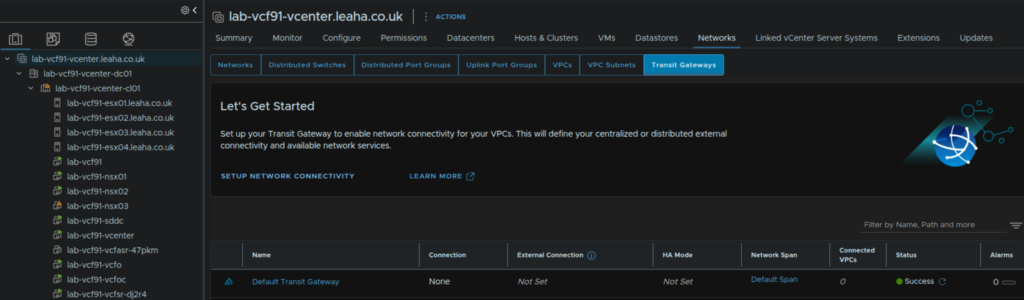
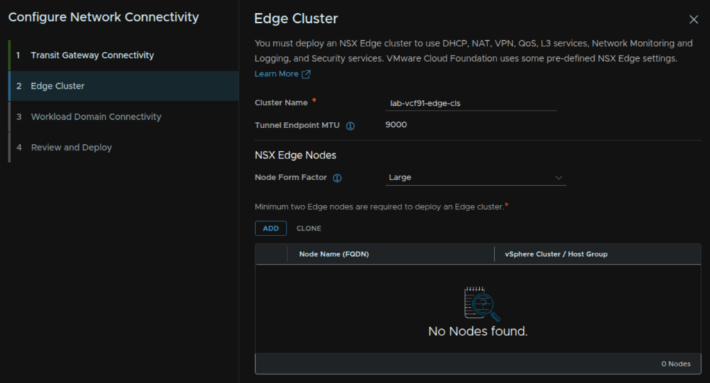
In vCenter, click the vCenter its self then Networks/Transit Gateways and click Setup Network Connectivity
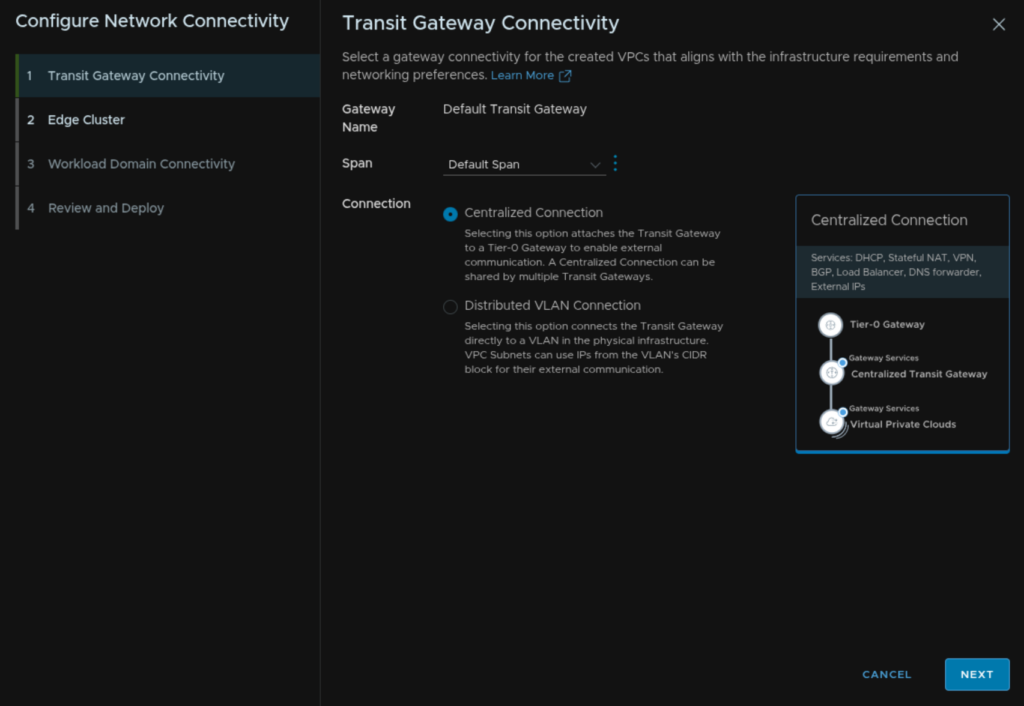
Select the Span to be the default, we can use spans to limit connectivity between certain vCenters within an NSX instance, but the default will set it for all, then set the Connection to Centralized Connection and click Next
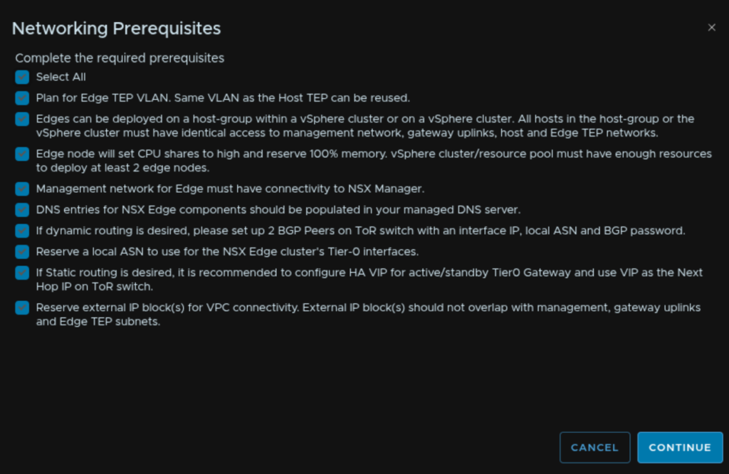
Check the Select All Box, reviewing the prerequisites, and click Continue
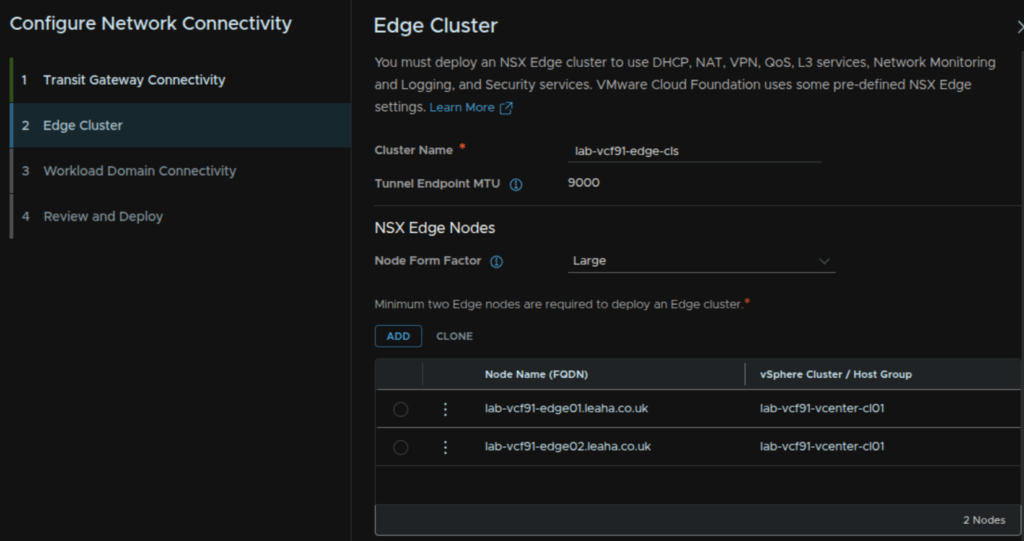
Give the Edge cluster a name, select the Large form factor, this will be needed for the Supervisor, and click Add
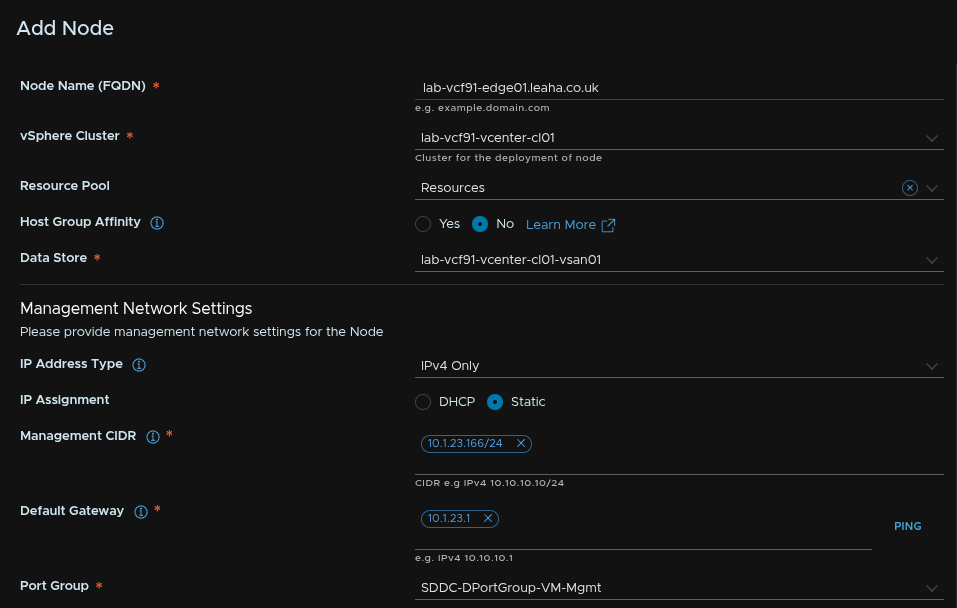
Enter the node FQDN, select the cluster, optionally add a resource pool, leave host affinity on No, we can configure this later, select a datastore
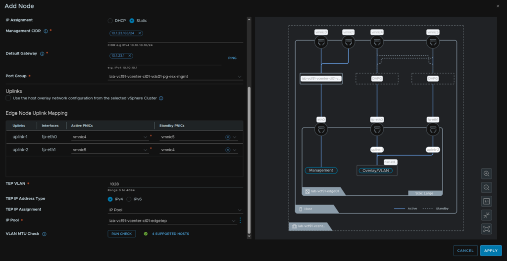
Then for the management IP select IPv4 only and click Static for the assignment, enter the management IP in CIDR address, add the gateway, then add the VM Management port group we set during the deployment, if you need to check its the port group vCenter is on
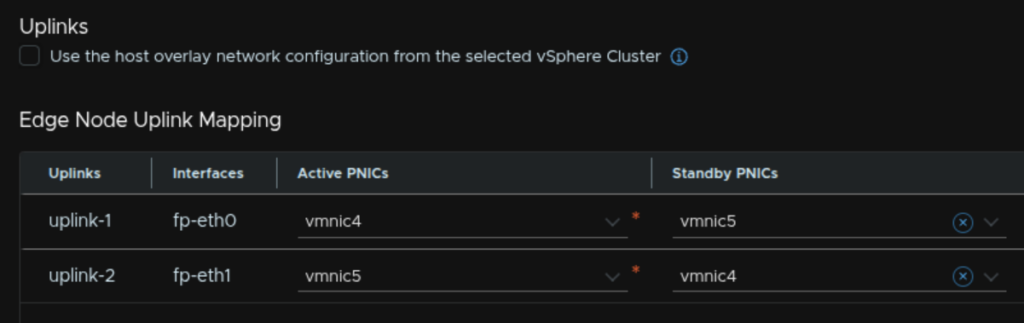
For the uplinks, uncheck the box to use the host overlay network the active/standby pNICs should alternate like this and will be populated by default
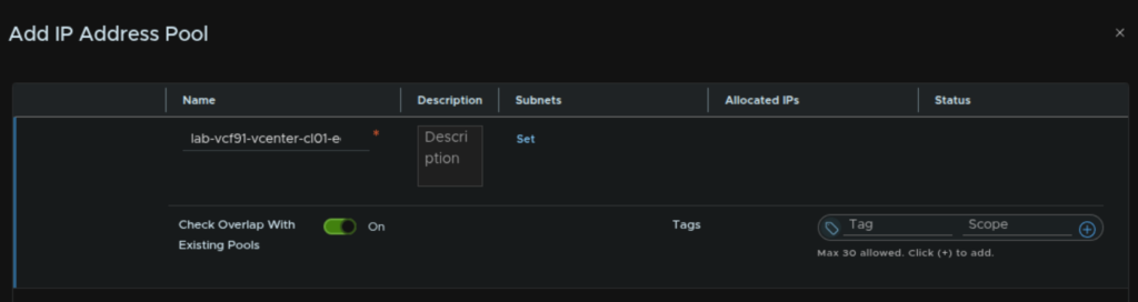
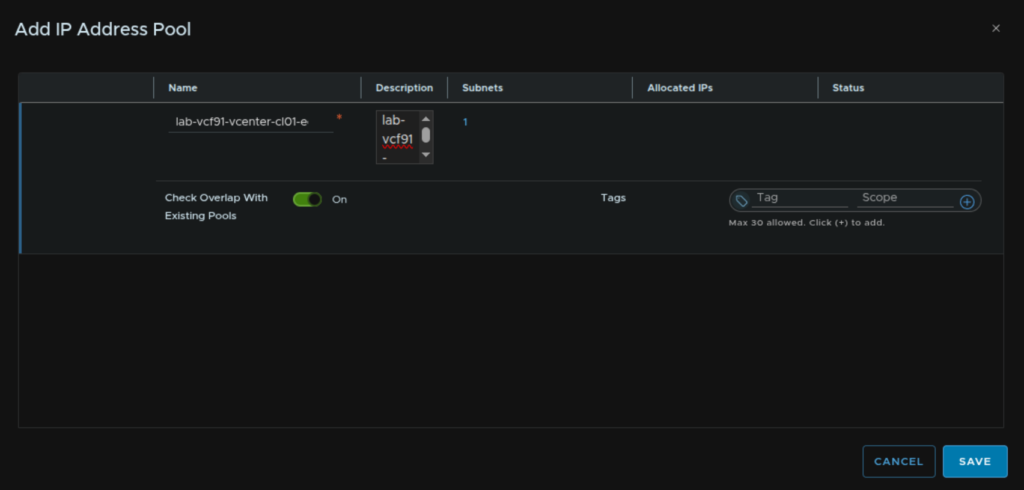
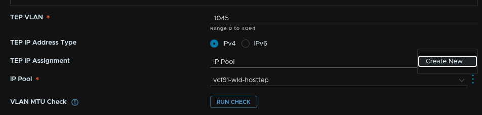
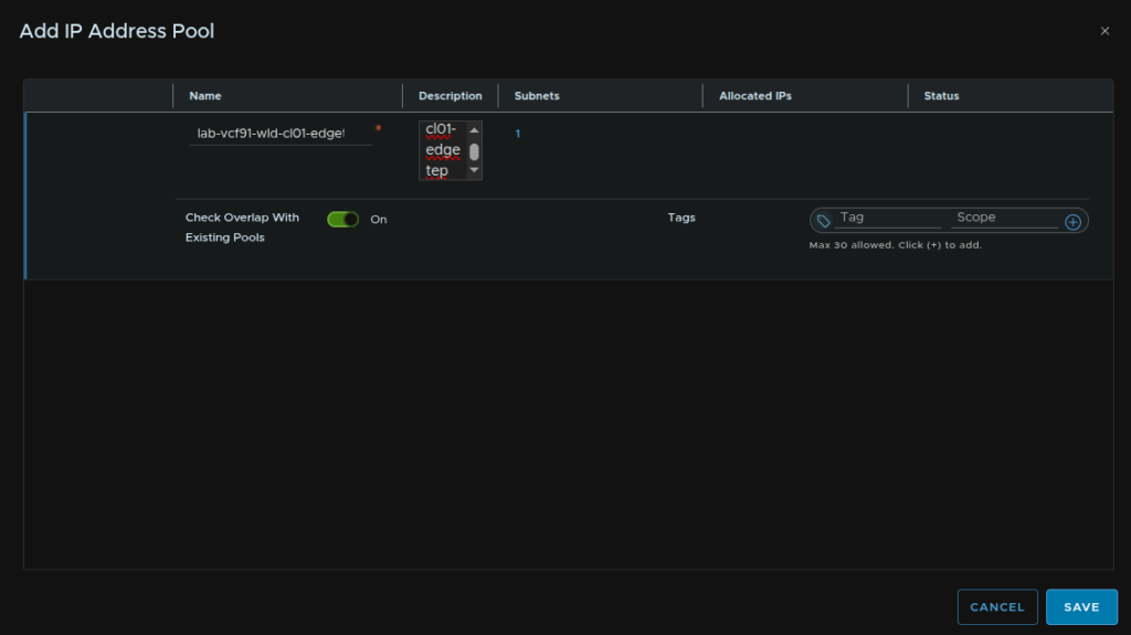
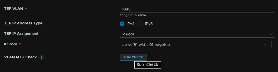
Enter the Edge TEP VLAN, for the IP Type, select IPv4, select IP pool, then click the three dots and click Create New
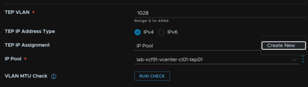
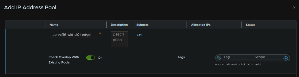
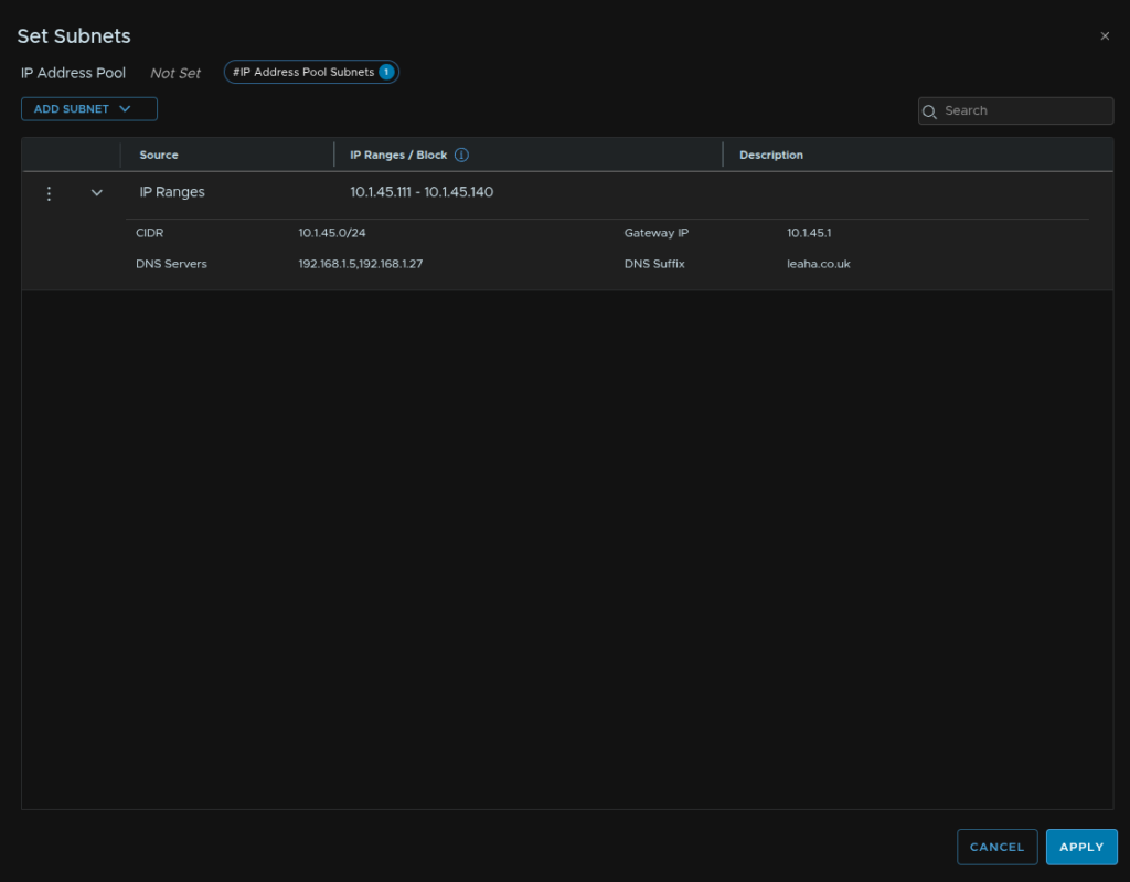
Give it a name and click Set under Subnets
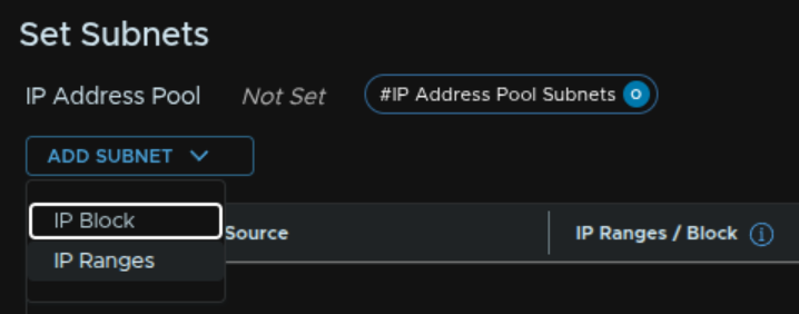
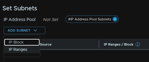
Click Add Subnet/IP Ranges
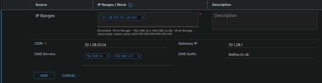
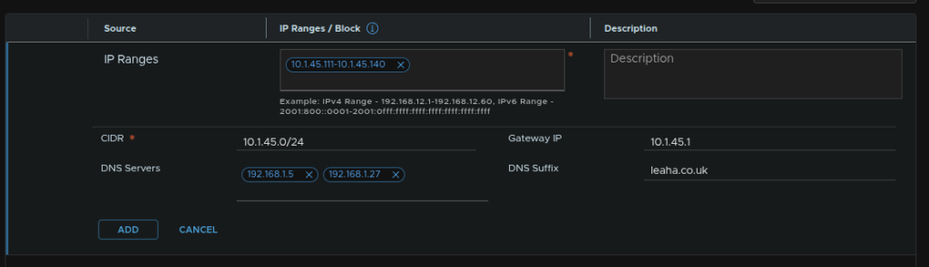
Add an IP range for TEPs, then add the network in CIDR notification, gateway, DNS servers and DNS suffix then click Add
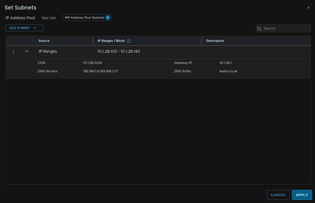
Then click Apply
Add a description and click Save
Now click Run Check to check the VLAN MTU
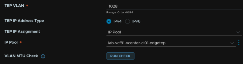
Then click Apply
And repeat for the second Edge Node, we wont need a new IP pool as we can select the new one from the drop down
Once thats done it should look like this

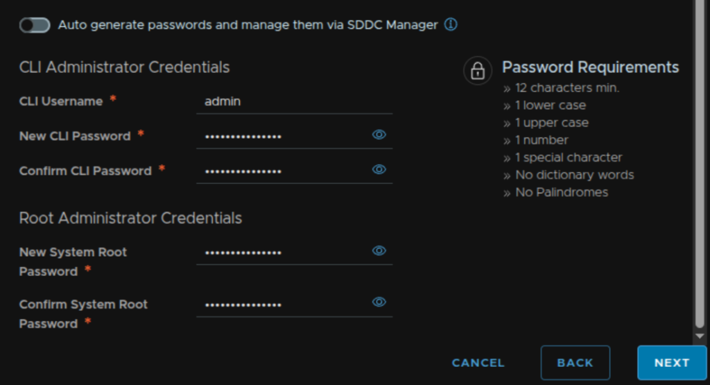
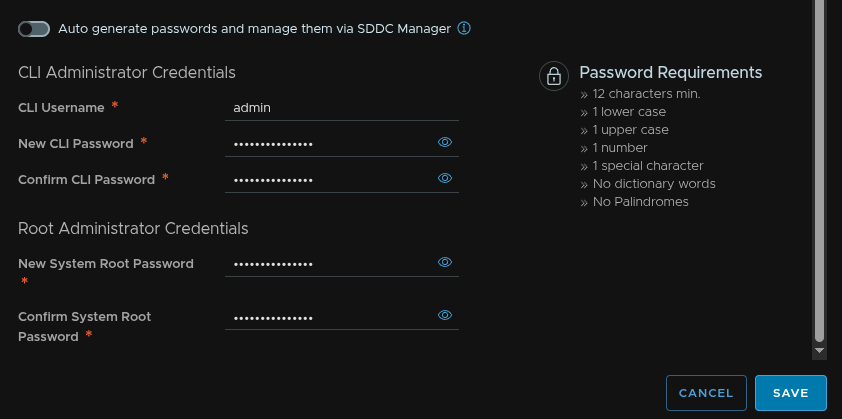
At the bottom we can remove the toggle to set our own passwords if we want to, when you are happy, click Next
We then need a name for the gateway, enter a name for the T0 gateway, keep HA on Active/Standby, this is very difficult to change later, and Active/Active isnt supported for the supervisor with VPC, routing needs to be BGP, and we then need a local AS number, this must be unique on your network
My lab router has ASN 65535 and thats all I have
But you might want something like ToR1 on 65534 and ToR2 on 65535
I used 65532 for the edge cluster
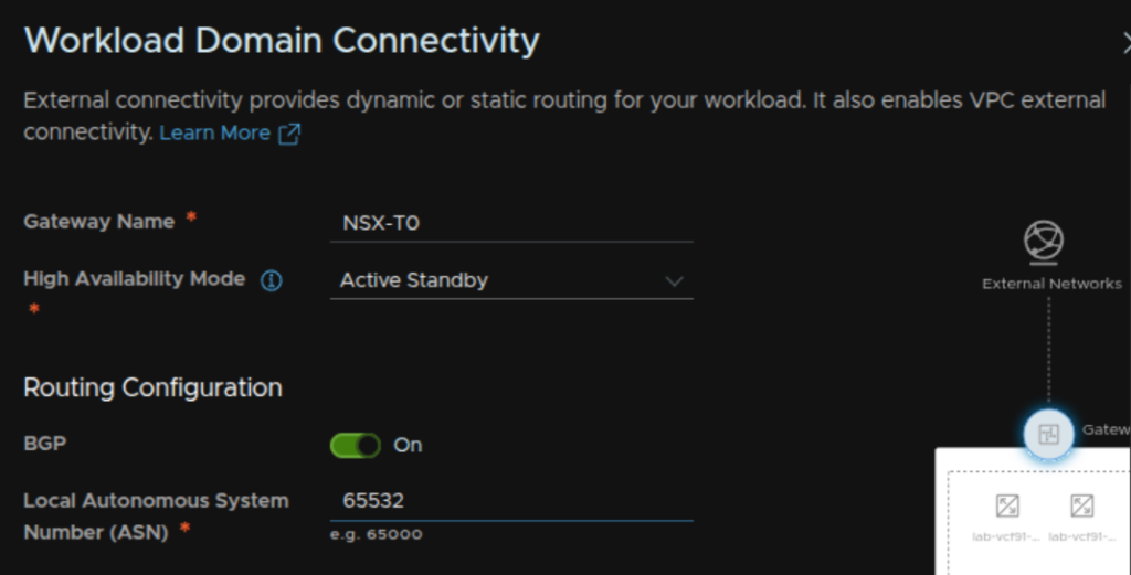
For gateway uplinks click Set
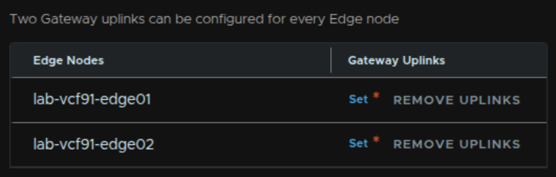
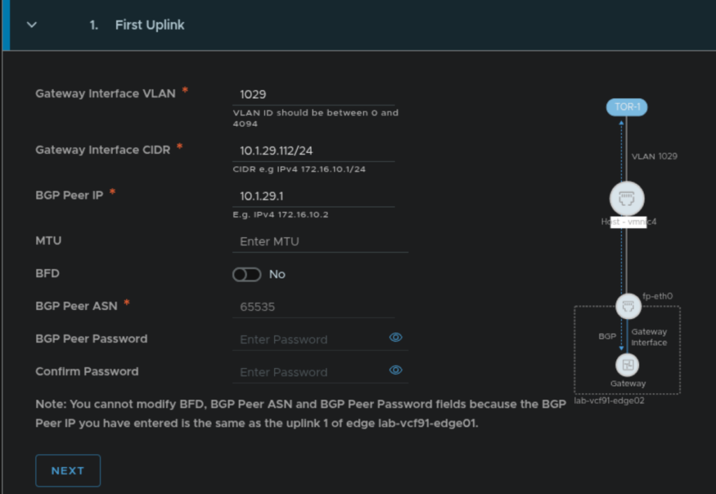
Now we need to enter the details for the Uplink 1 VLAN
Enter the VLAN ID, interface CIDR, this is the UP the Edge will have and much be unique, gateway IP the ToR has, and enter the ASN number configured on ToR1, then click Next
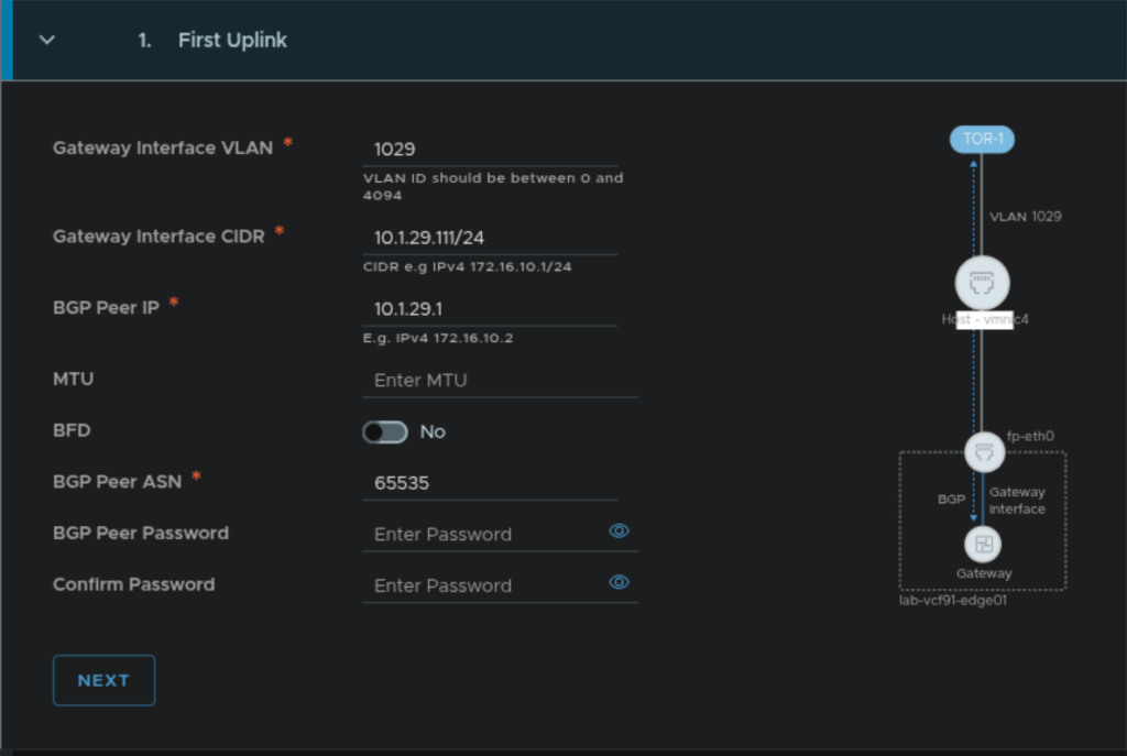
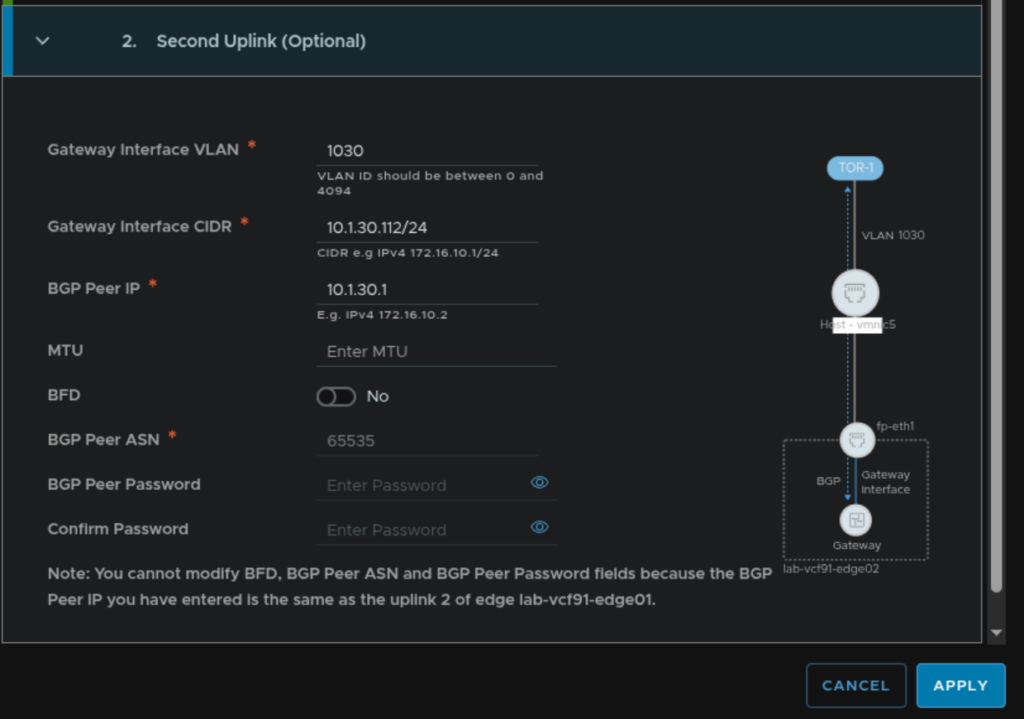
Repeat for Uplink 2 and click Apply
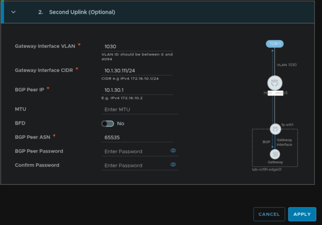
The same config should be applied to the other Edge node
Uplink 1
Uplink 2
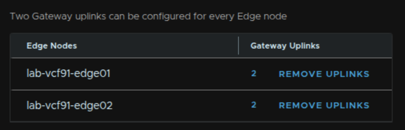
When its done it should look like this
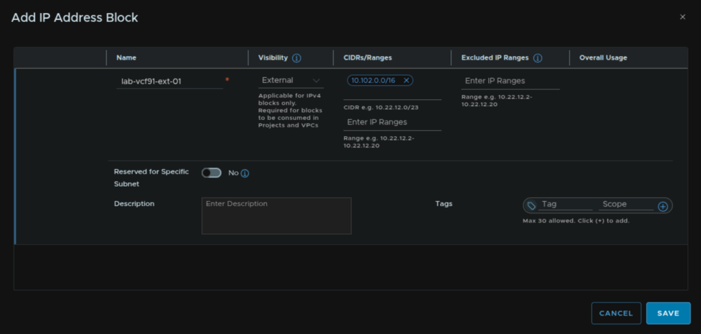
We then need our VPC connectivity, we need two large subnets, I recommend /16s, these must not overlap anywhere else on your datacenter, that can be split out as needed within VPCs, these blocks should not overlap anywhere else on your network
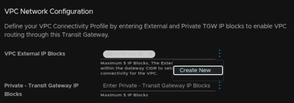
For VPC External IP Blocks, click the three dots and click Create New
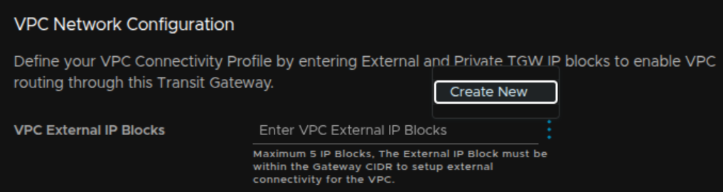
Enter a name and add the CIDR, I opted for 10.102.0.0/16 and click Save
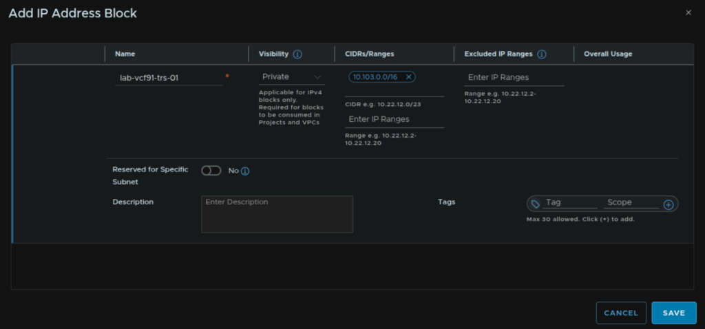
Repeat for the transit gateway blocks clicking the three dots and click Create New
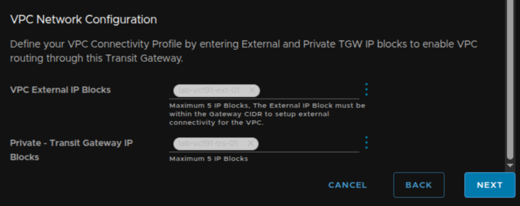
Add a name and the IP block, I opted for 10.103.0.0/16, then click Save
Then click Next
Review the config and when you are happy, click Deploy
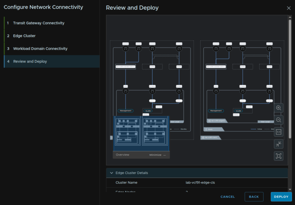
You will need to update your BGP config on the ToRs with the addresses the Edges have on each uplink VLAN so BGP is then communicating properly
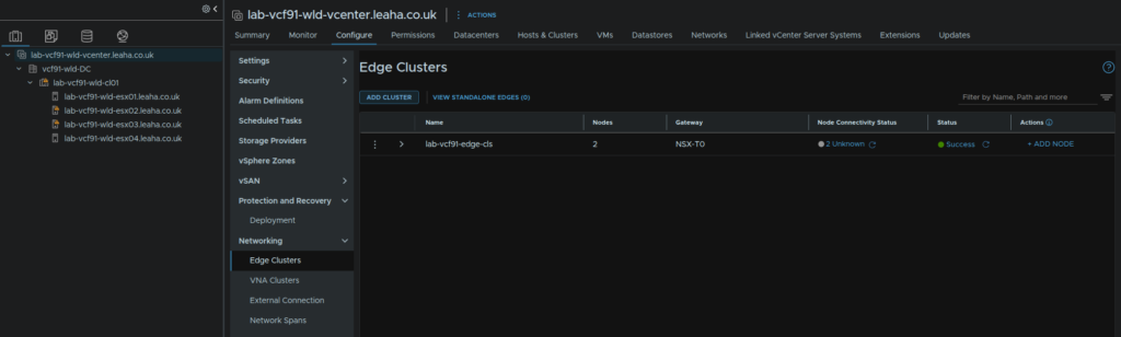
We can click View Details to see the deployment
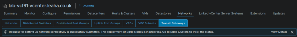
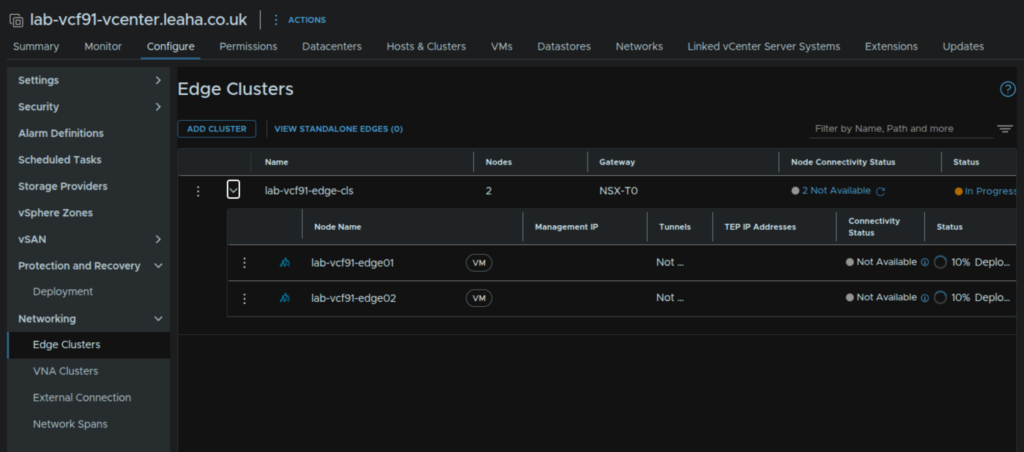
This takes us to Configure/Networking/Edge Clusters
4 – Supervisor/VKS
If you want the Avi loadbalancer, you’ll need to revisit this later, else you’ll get the NSX loadbalancer and this cannot be changed after its deployed
You can either deploy this via VCF Operations or standalone, VCF Ops doesnt manage the lifecycle and so it doesnt have to be deployed using it
To get access to K8S in vSphere, or the new All Apps organisation type in VCF Automation, we need the supervisor deploying
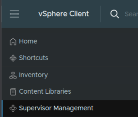
In vSphere, click the three lines in the top left and click Supervisor Management
Then click Get Started
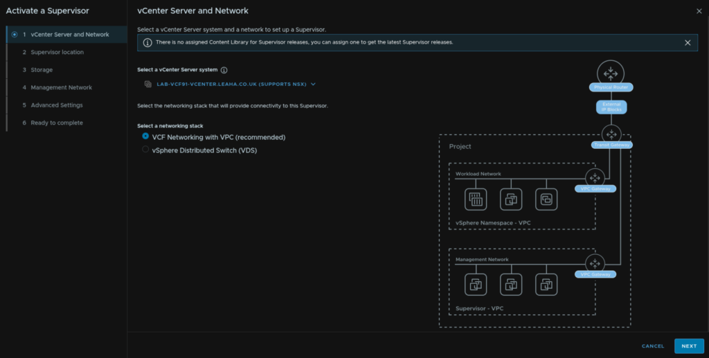
Make sure you have selected VCF Networking With VPC and click Next
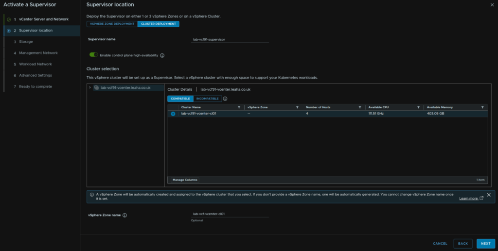
Click the Cluster Deployment tab, then enter a name for the supervisor, make sure the toggle is selected for control plane HA, select the cluster, and optionally provide a zone name, I recommend the cluster name, it must be all lower case, if you dont enter one, the system will generate one and it cannot be changed
Then click Next
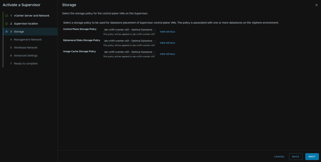
Select storage policy for all objects, I recommend the vSAN default for a 4 node or less, or you can use the ESA default, likely RAID 5 on a 5 node cluster or larger, then click Next
If you are using VMFS you will need to create your own and this must be a thick provisioning policy, thin can be used for deployments within namespaces however
Then click Next
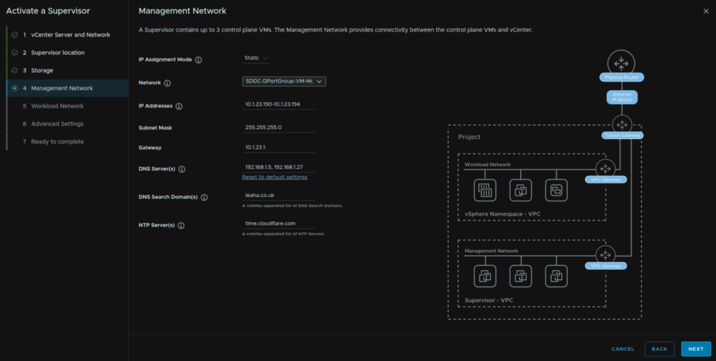
For the control plane networking, set the mode to static, then select the VM Management port group all our VMs like VCF Ops and vCenter are on, then enter a block of 5 IPs, add the subnet mask, gateway and DNS search domain, DNS/NTP should be pre populated, if not add them, comma separated, then click Next
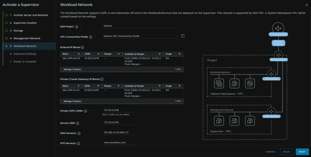
The NSX project and VPC connectivity profile should be automatically populated with the External and Private Transit gateway IP blocks
We then need private VPC blocks for the workload, this can overlap with any other network, I recommend a /16, I used the default of 172.30.0.0/16, the service CIDR can be left at the default, then add your DNS/NTP servers, comma separated and click Next
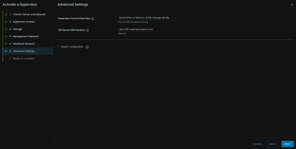
For the control plane size, small should be fine for most environments, we can add a DNS registered FQDN for accessing the API, we will need at a later point during the Supervisor configuration guide, for now ensure this isnt bound to any IP, then click Next
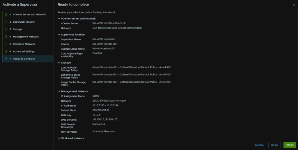
Then review and when you are happy click Finish
5 – Log Management
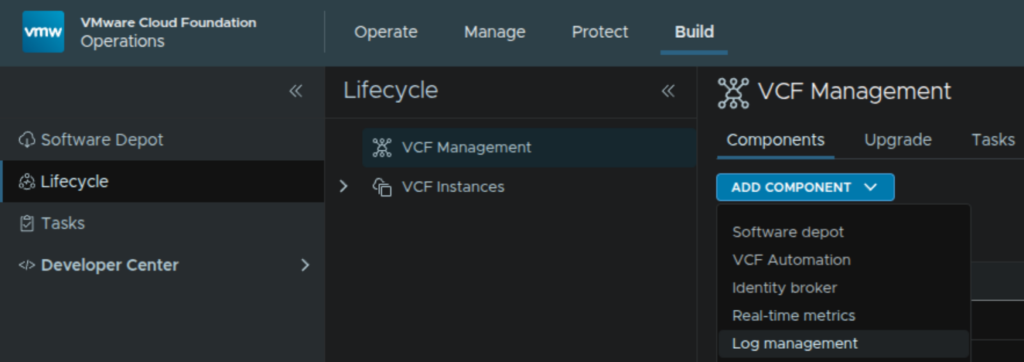
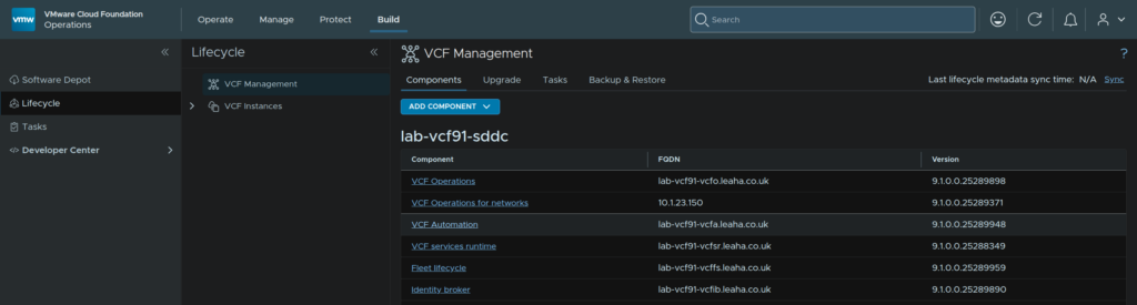
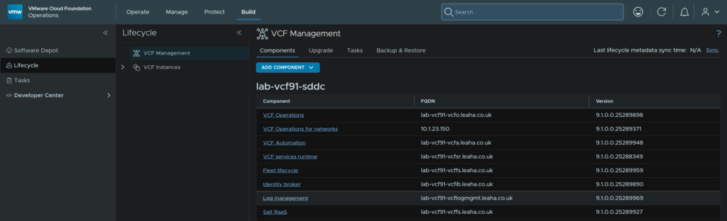
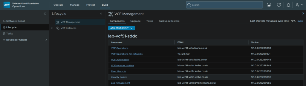
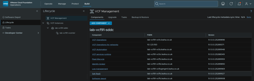
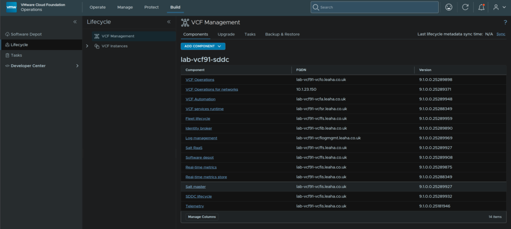
Log into VCF Operations, and head to Build/Lifecycle/VCF Management/Components/Add Component/Log Management
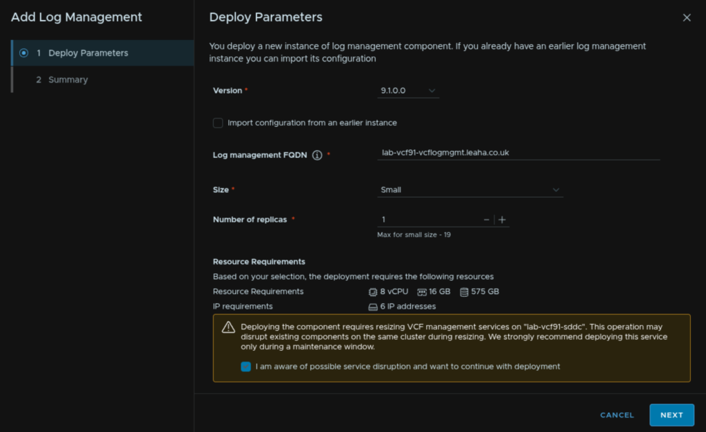
Select the version, in this case 9.1.0.0, give it a FQDN, this needs to be DNS registered, select the size, this affects the IP requirements and resources, adding this will also resize the Service Runtime appliances, its all K8S under the hood, check the box to acknowledge service interruptions and click Next
Its worth noting, the resource requirement will cause the management services, the K8S cluster, to be automatically resized as capacity is needed. in this case an extra worker node is deployed using 12vCPU and 24GB RAM
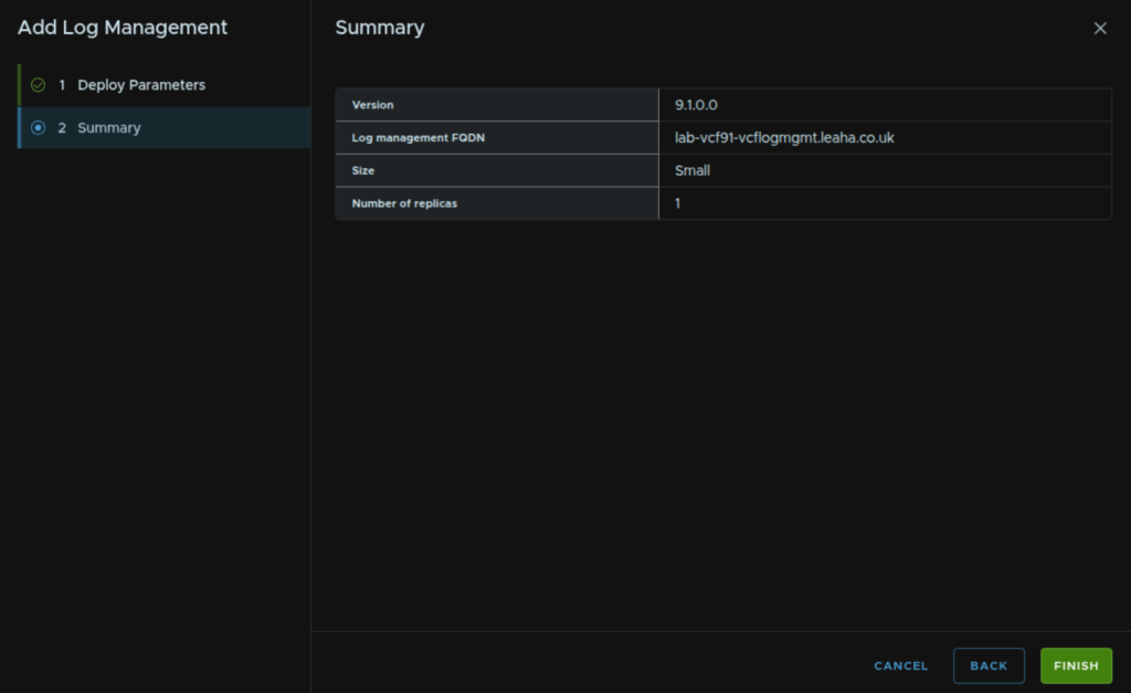
Then click Finish
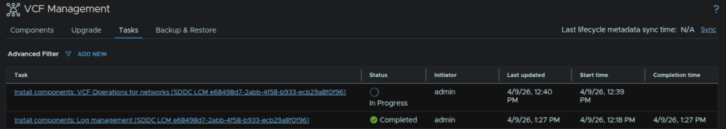
This will take a while to install, but we can see when its done from the Tasks pane
6 – VCF Operations For Networks
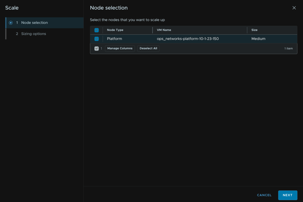
Log into VCF Operations, and head to Build/Lifecycle/VCF Management/Components/Add Component/VCF Operations For Networks
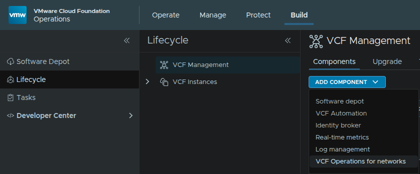
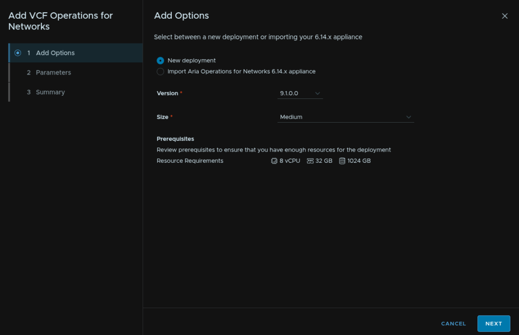
Select the size, we will need at least a medium size, then click Next
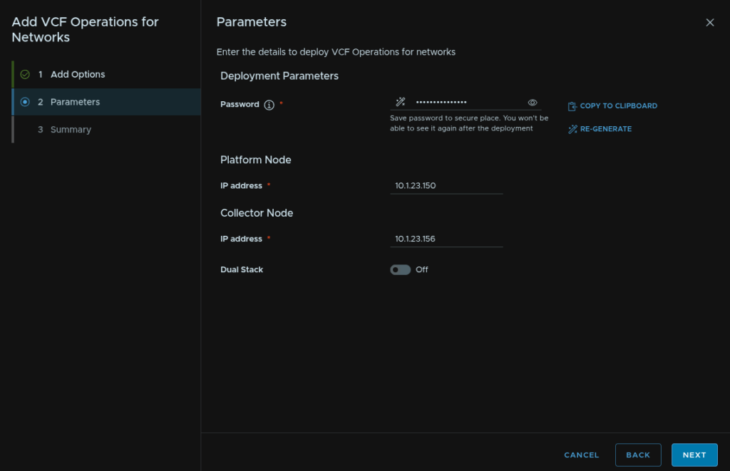
Set a password for the admin user, it can also generate one if needed, then enter an IP address for the platform node and collector, these IPs need to be on the same network as vCenter, then click Next
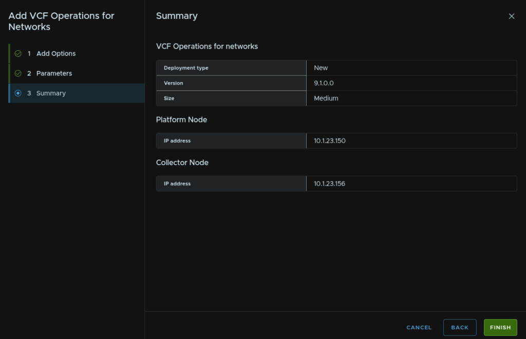
And click Finish
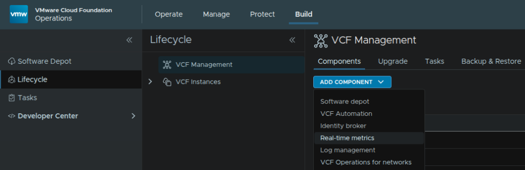
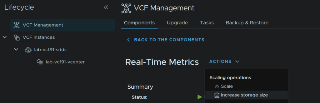
7 – Real-Time Metrics
Log into VCF Operations, and head to Build/Lifecycle/VCF Management/Components/Add Component/Real-Time Metrics
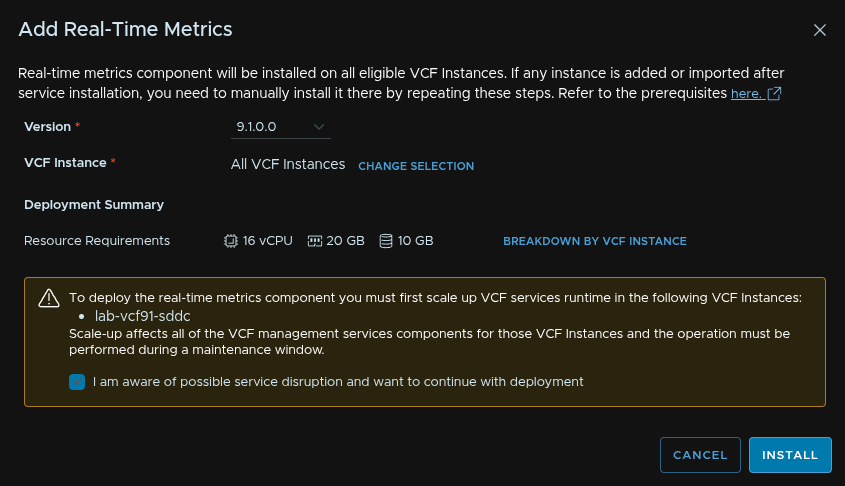
Select the deployment version, in my case 9.1.0.0, leave VCF instances on All VCF Instances unless you want to exclude any, and check the box to knowledge the VCF service runtime resize and click Install
Its worth noting this will result in another worker being deployed into the services runtime at 12vCPU and 24GB
8 – vSAN ESA Snapshot Appliance
9 – Post Deployment Steps
9.1 – Expanding The VCF Services Runtime
This K8S cluster hosting a large sum of components can be scaled if you did a simple deployment when building the VCF instance, the key difference is the K8S control plane consists of a single server, 4vCPU/10GB, and can be scaled to a HA 3 node cluster
I would recommend scaling this to HA on the control plane in a production environment
Its also worth noting, during this deployment I did notice one additional worker node, the 12vCPU/24GB VMs, get deployed so scaling this can have larger requirements than just the control plane cluster
Also, after scaling this to medium, the worker nodes were slowly replaced
I would recommend scaling this if you are planning to scale components running on this platform beyond the minimum, this includes
- Log Management
- Real Time Analytics
- Identity Broker
- Salt
- Software Depot
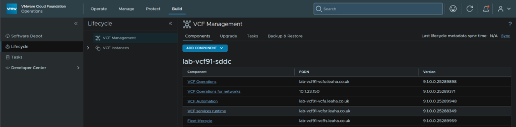
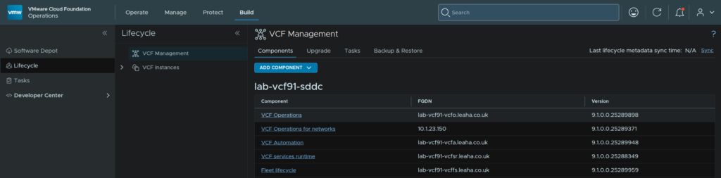
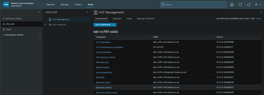
To begin, log into VCF Operations and head to Build/Lifecycle/VCF Management and click VCF Services Runtime
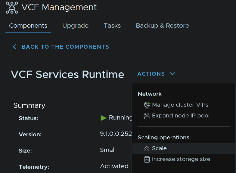
Click Actions/Scale
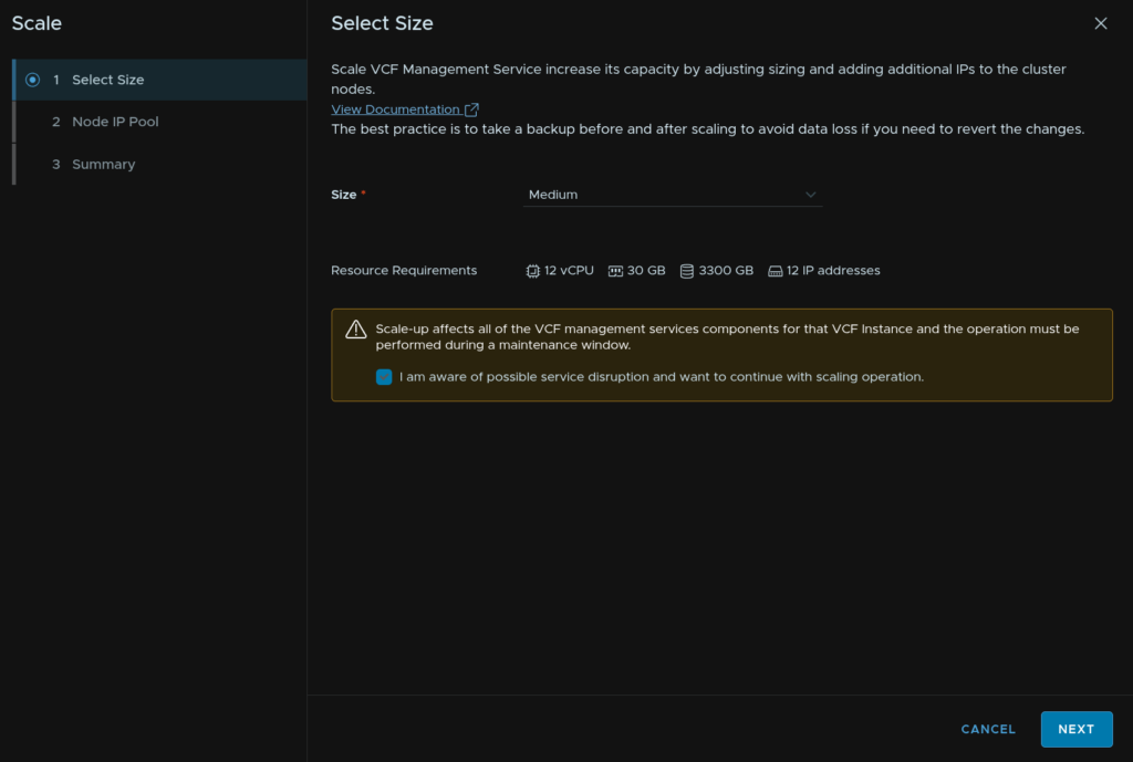
Select the Medium Size, unless your VCF Fleet is massive Large is very overkill, check the box to acknowledge potential service interruption and click Next
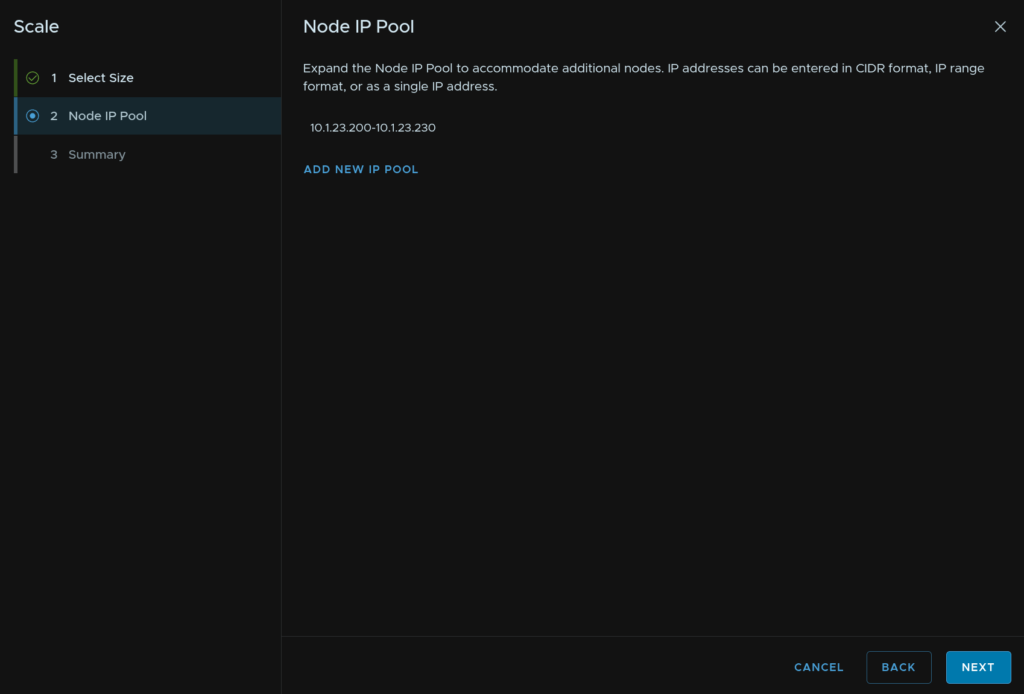
We can add additional IPs if needed, as we deployed this with an IP pool of 30, meant for the larger scales, we can just click Next as we have plenty of IPs
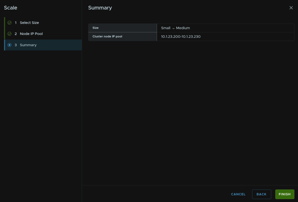
And click Finish
9.2 – Configuring Log Management
Now that we have the environment and Log Management deployed, we need to onboard our domains so they log to the Log Management cluster
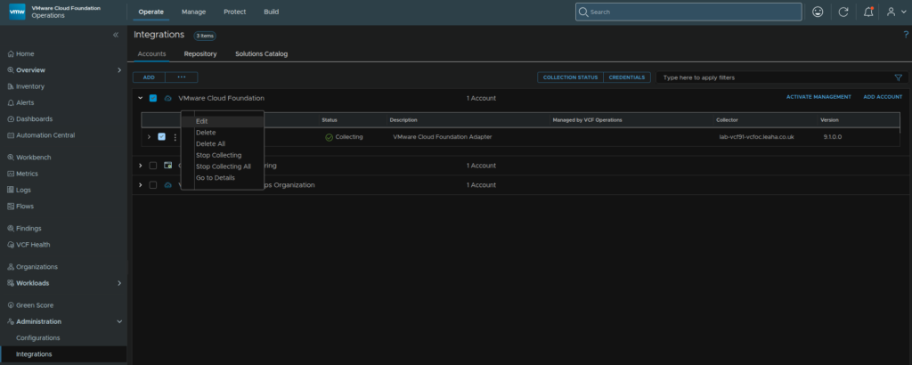
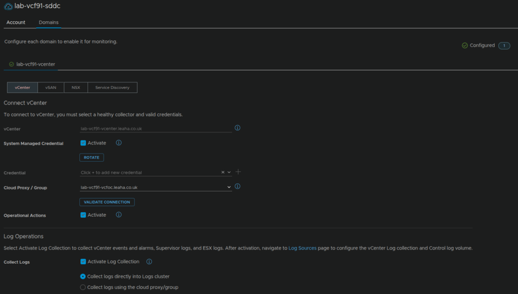
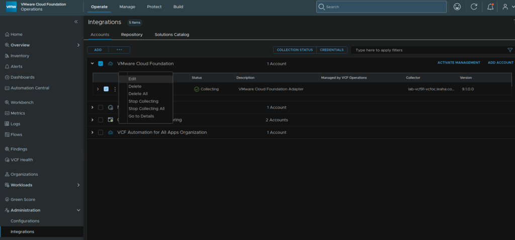
Head to Operate/Administration/Integrations, expand VMware Cloud Foundation, and click the three dots on your VCF instance and click Edit
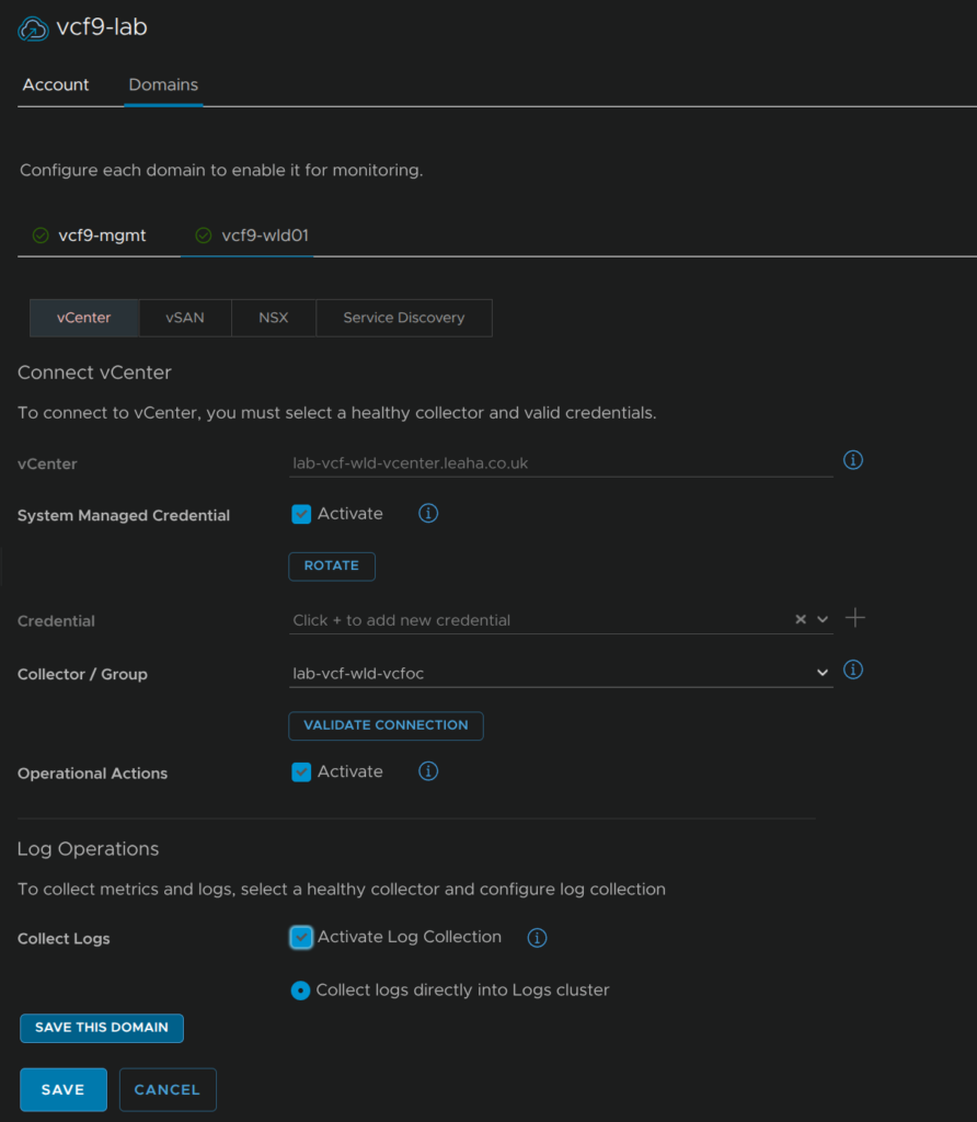
Click Domains, here we will then see all our domains, you will be on the vCenter by default, under Log Operations, click Activate Log Collection, and select the radio button to bring them directly into the cluster
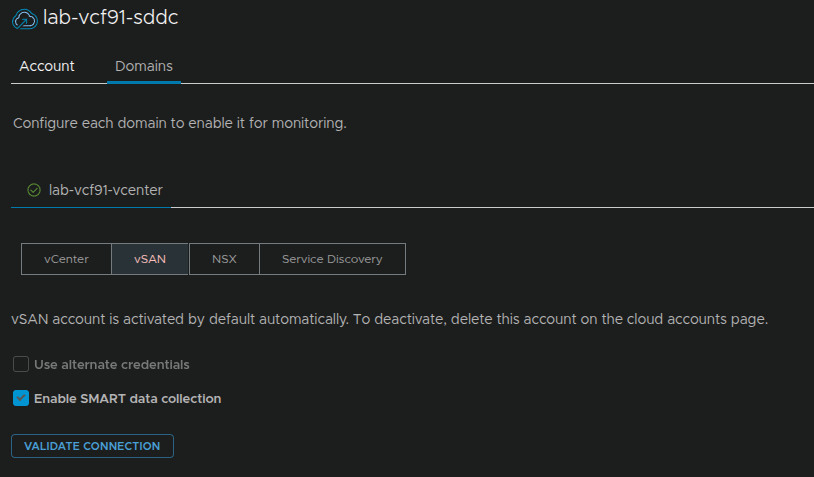
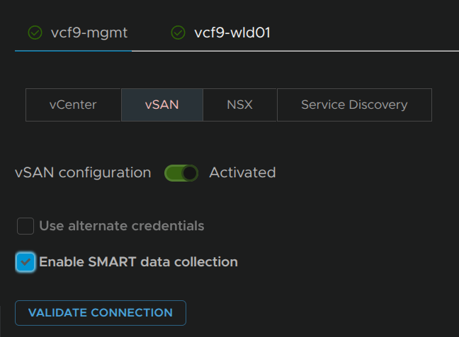
On vSAN, if you have it, check the box for Enable SMART Data Collection
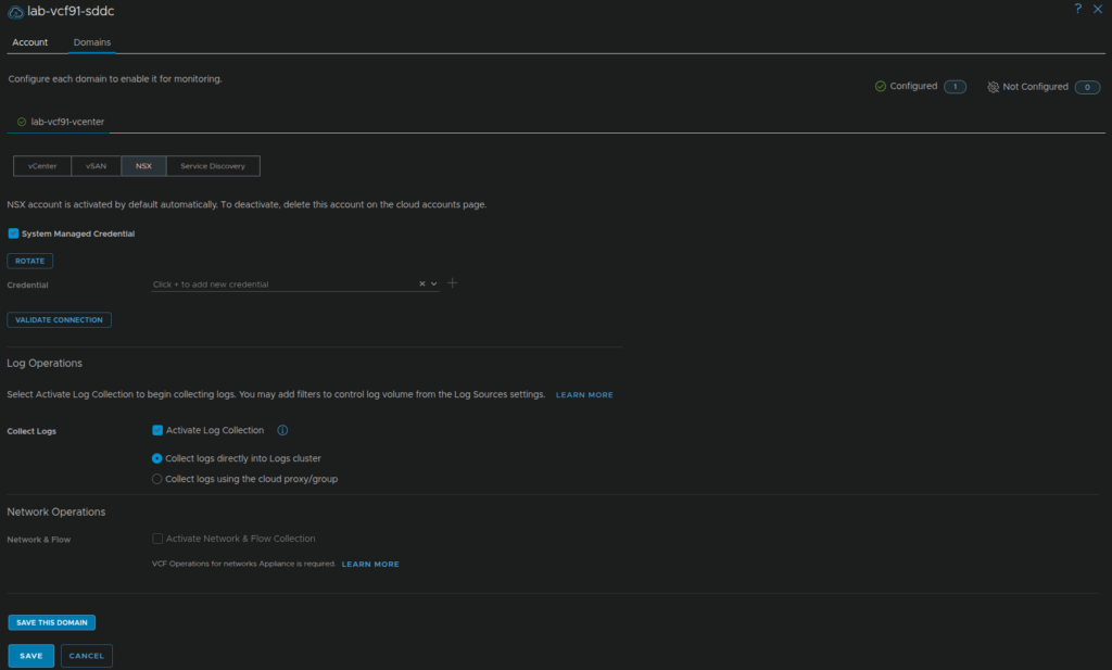
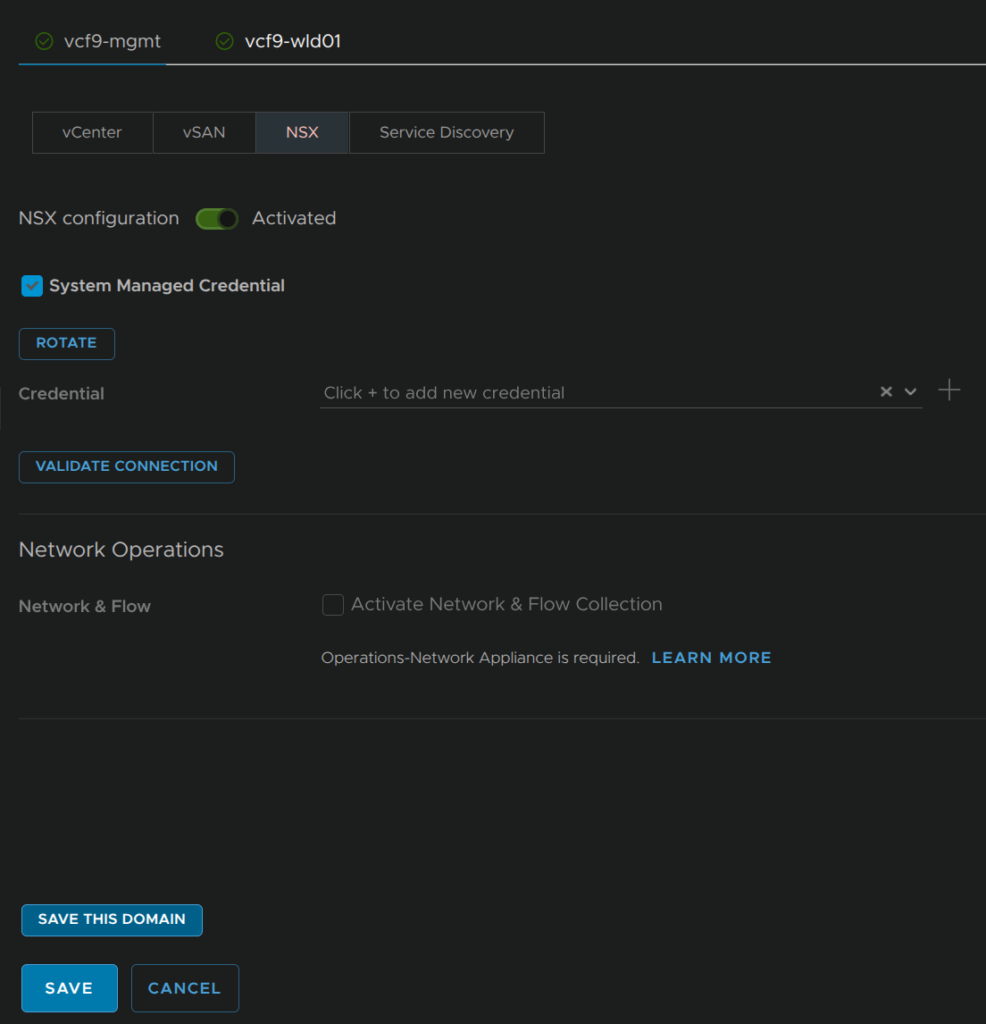
And for NSX do the same as vCenter and click Save
9.3 – Configuring VCF Operations For Networks
Now that we have the environment and Log Management deployed, we need to onboard our domains so they log to the VCF Operations For Networks cluster
Head to Operate/Administration/Integrations, expand VMware Cloud Foundation, and click the three dots on your VCF instance and click Edit

Click Domains, here we will then see all our domains, you will be on the vCenter by default, under Log Operations, click Activate Network And Flow Collection, select our collector, then click the check box to Enable NetFlow on the vCenter

Click Enable
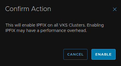
Repeat for the Antrea IPFIX and check the box
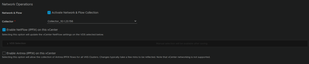
And click Enable
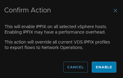
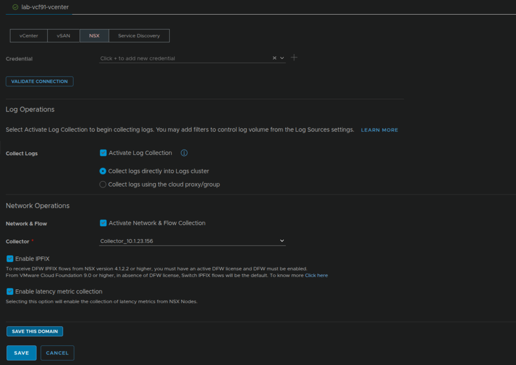
Click NSX at the top, and check the box for Activate Network And Flow Collection, select the collector and check the box to enable IPFIX
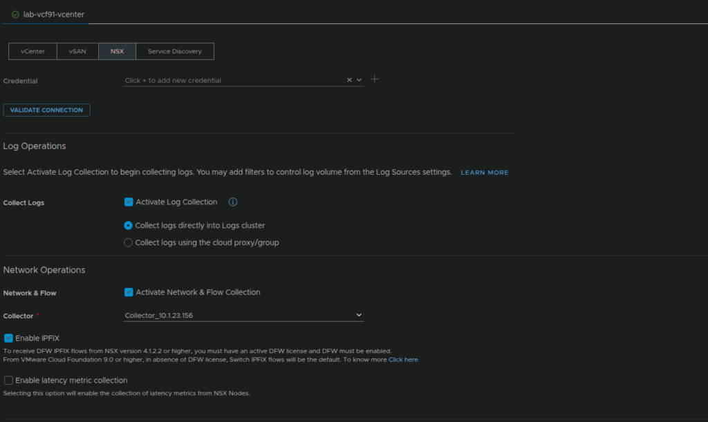
Then check the bot for latency collection and click enable
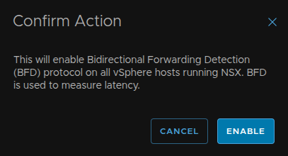
Then click Save
9.4 – Backups
9.4.1 – vCenter
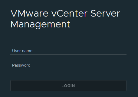
The best practices method to backup a vCenter is to use the config backups in VAMI
To access VAMI go to the following link substituting fqdn for your vCenters FQDN
https://fqdn:5480
You can log in here with the local root account, or an SSO admin login
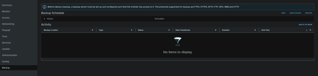
Now head to the backups tab at the bottom on the left, from here you can click ‘Configure’ on the right to setup a schedule
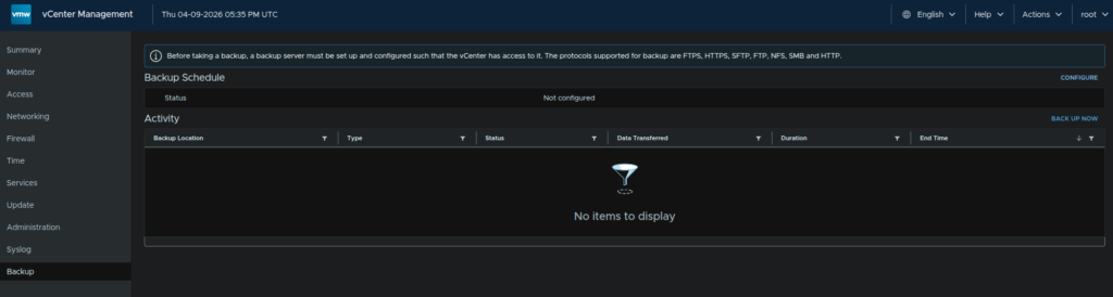
You’ll need a valid backup location to store them, an SMB, NFS or FTP server work best but you can also use HTTPS and FTPS
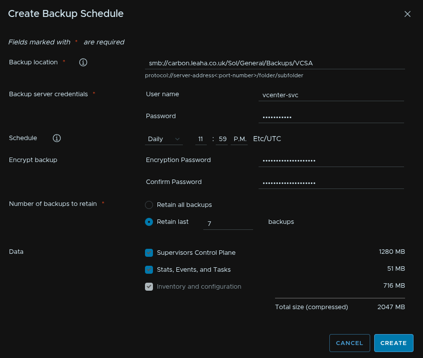
The backup schedule will give you a format for the backup location

We want to setup our location, here I am using an SMB server, but for NFS/SFTP the process is the same you just change the protocol at the start to NFS or SFTP respectively
We can also add in an account with read/write permissions to the share, I recommend a service account with a password that wont expire, as if it expires and you forget, the backups will stop working
Enter a password encrypt the backup, however you must not loose the password else you cant restore it
You’ll want it to run daily, ideally if you need to restore you dont want a backup older than 24 hours
Retain the last 7 backups, this will remove older backups and maintain its self
And check all boxes at the bottom to back up everything
Then hit create
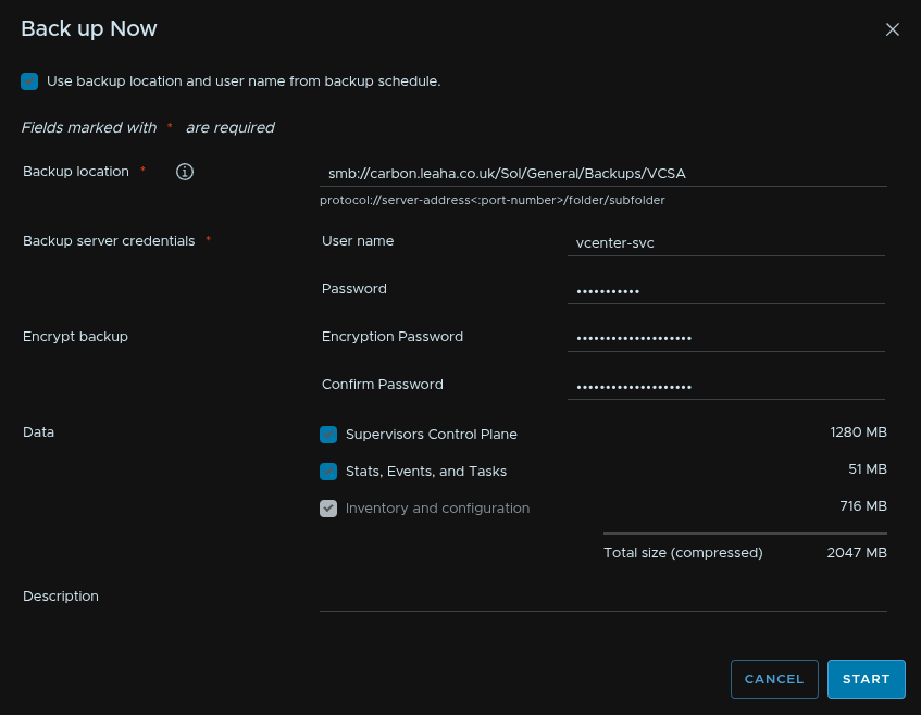
To test this works, run a manual backup by clicking Backup Now on the right
Click use backup location and username at the top of the pop up, this will pull the settings from the schedule, you’ll just need to enter the account password
Then click start
9.4.2 – VCF Management Services
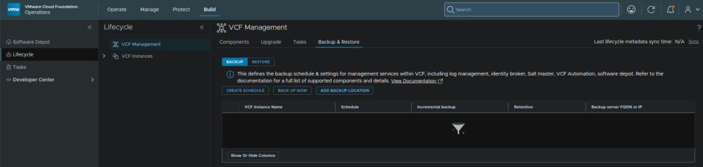
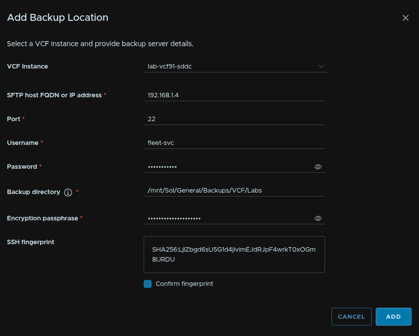
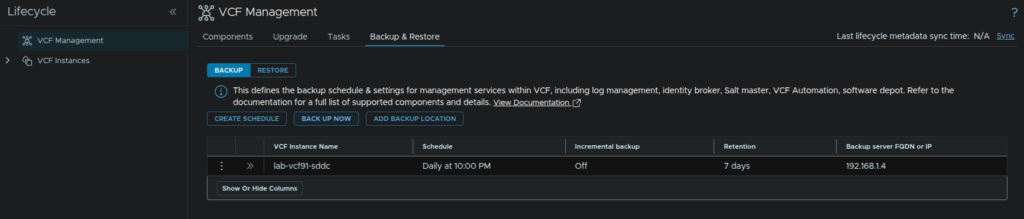
VCF Management can be easily backed up from VCF Operations, click Build/Lifecycle/Backup & Restore then click Add Backup Location
Select the VCF instance, add the SFTP server IP address, the port will be 22, add a username for the backup account, and its password, I recommend a service account, then add the directory to be backed up to, and a strong encryption password, you must not loose this, then click Add
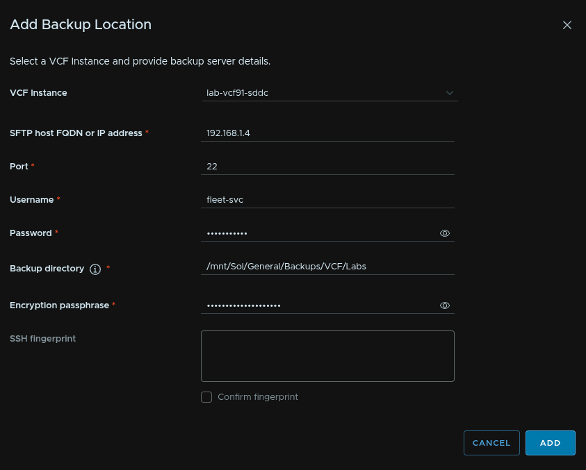
Now check the box to confirm the fingerprint and click Add again
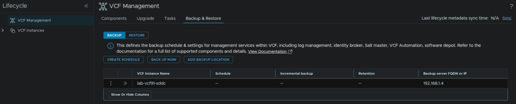
This will take a while but can be viewed from the tasks section, when its done it will look like this, then click Create Schedule
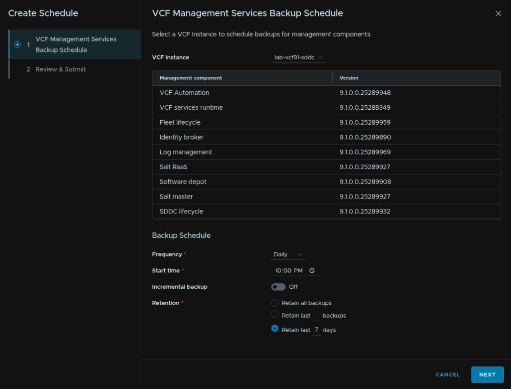
Select your VCF instance, then select the frequency from Daily or Weekly, set a start time, optionally configure incremental backups which can run every 1-4 hours, and for the retention, set this to the last 7 days and click Next
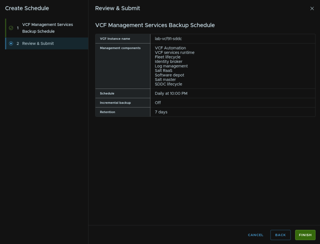
Then click Finish
We then need to wait for the schedule to finish, we can again see this in tasks, but when its done it will look like this
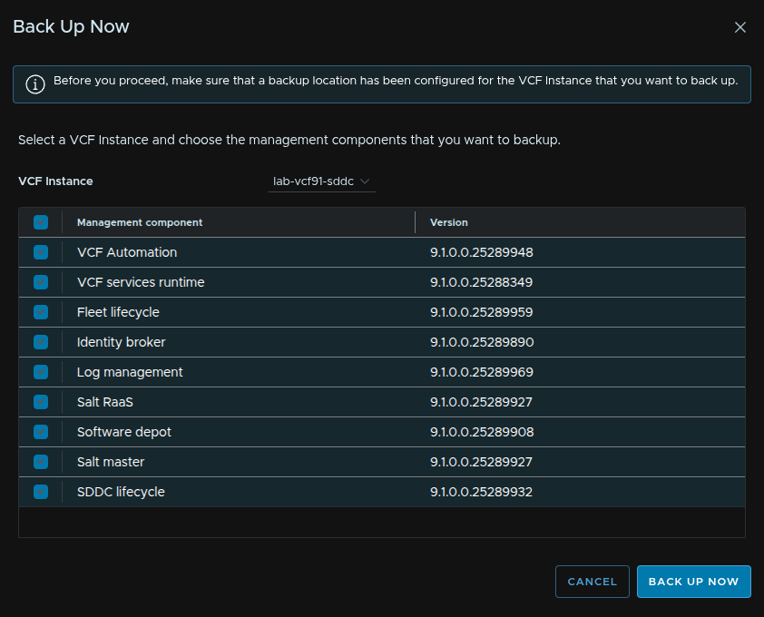
To make sure it works click Backup Now
Select your VCF instance and select all components, then click Backup Now
9.4.3 – SDDC Manager And NSX
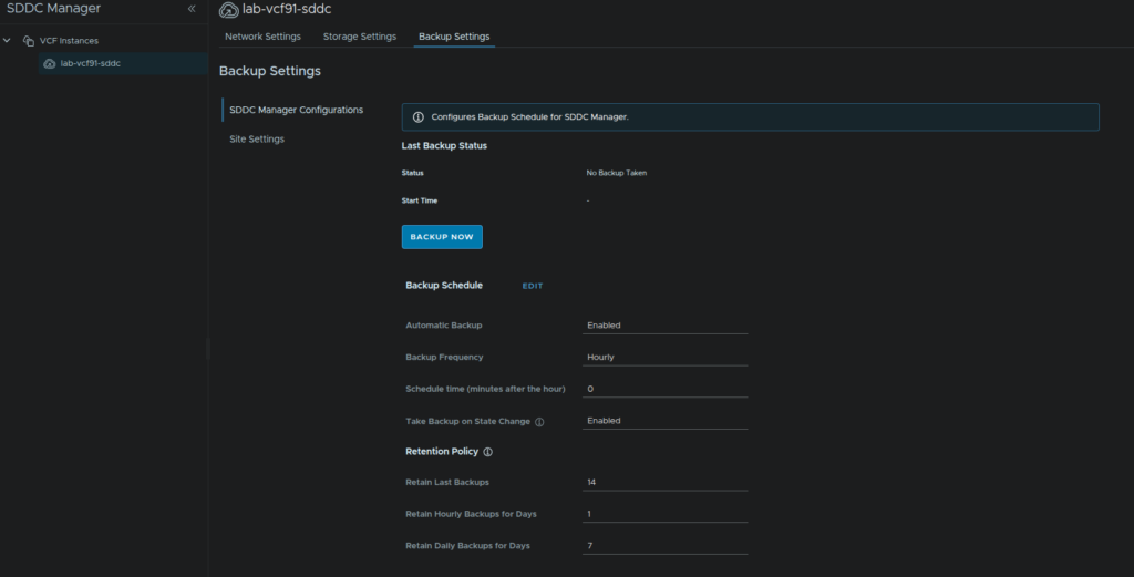
To amange these backups, click Operate/Administration/SDDC Manager then click your VCF instance, now click Backup Settings/Site Settings
Enter the IP address of the SFTP server, the port which is 22, the protocol which is SFTP, username which should be a service account with its password, then a directory to store the files, confirm the fingerprint, and add an encryption password, then click Save
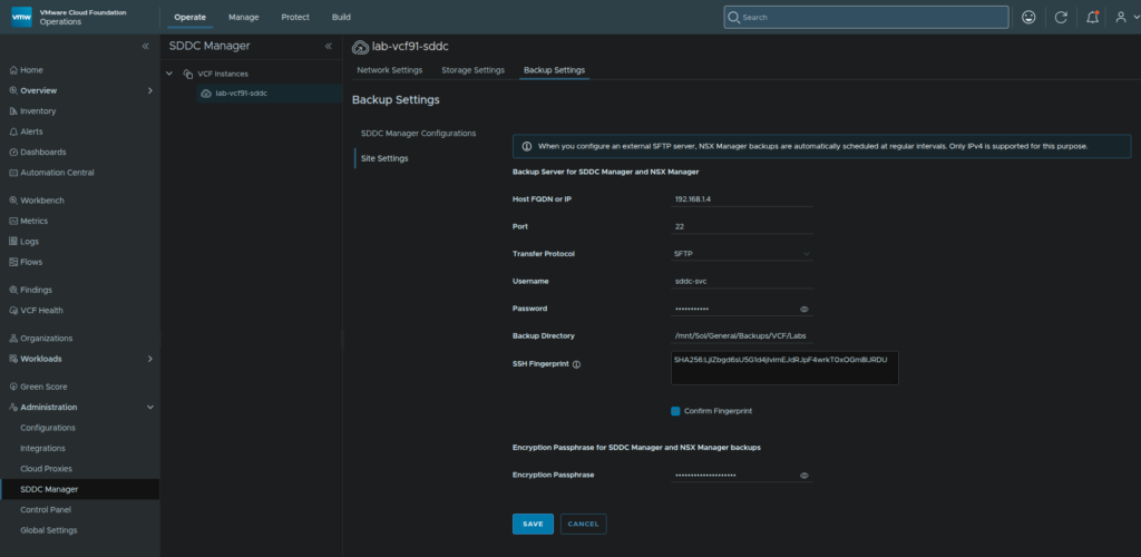
Click Confirm

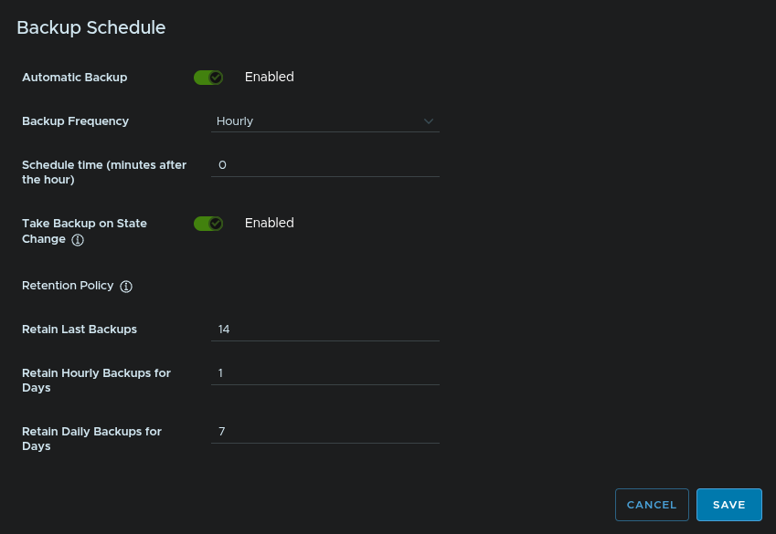
If we head to SDDC Manager Configurations, the option to click Backup Now will be available once the Site Settings we just set are configured and we can click Edit on Backup Schedule
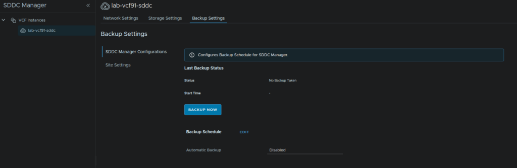
Enable Automatic Backup, set the frequency to Hourly or Weekly, I recommend Hourly, set the number of mins after the hour to backup, I went for 0, enable Backup On State Change, and enter the number of backups to retain, how many days to retain hourly backups and days to retain daily backups then click Save
Wait for that to configure, then click Backup Now
9.5 – Licensing
This section was done on another environment due to licensing constraints, FQDNs will not match the rest of the guide
Its worth noting, vDefend licensing is no longer done by a key in NSX, it requires a different licensing server deployed by the Security Services Platform, requiring 6vCPU and 24GB RAM
It has been excluded from this section due to it being a paid add on and will be included in the vDefend configuration guide, though there is no ETA on this
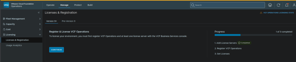
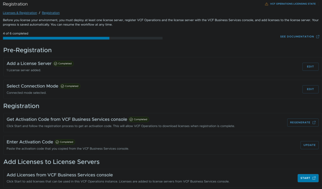
To license our environment we need to log into VCF Operations and click Manage/Licensing/Licenses & Registration then click Continue
Then click Start
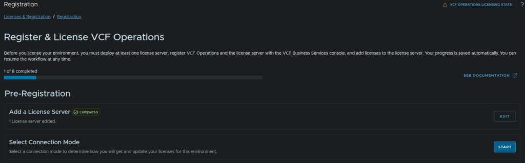
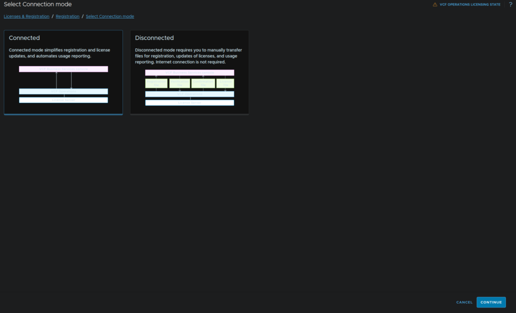
Click Connected and click Continue
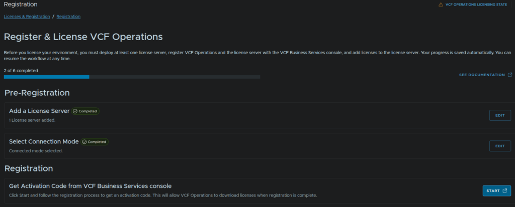
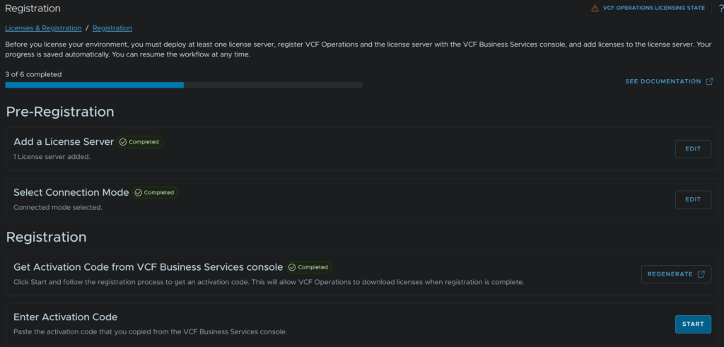
Now click Start again under Registration
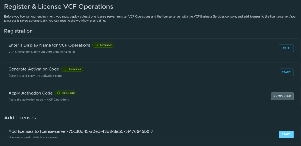
Log into the Broadcom portal and click Start
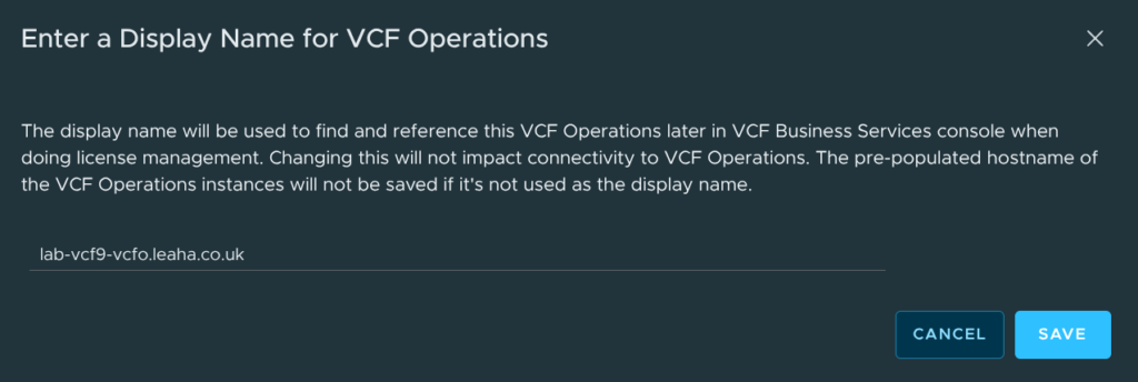
The screenshot below may automatically appear
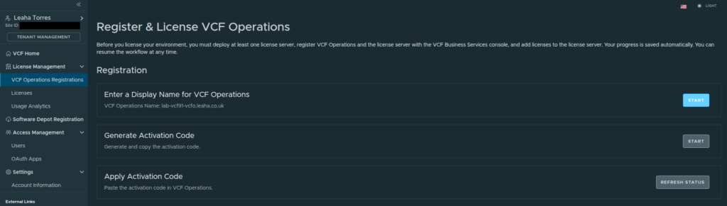
We can use the VCF Operations name and click Save
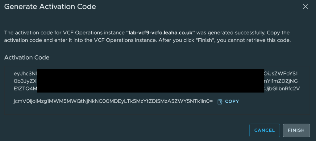
Click Start on Generate Activation Code
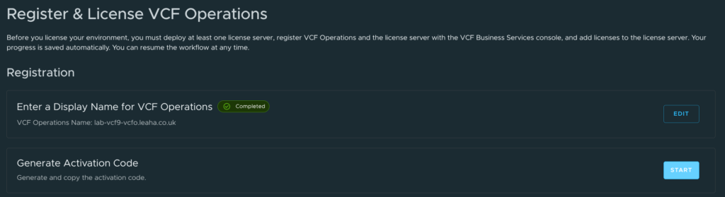
Click Copy to copy the code, then click Finish
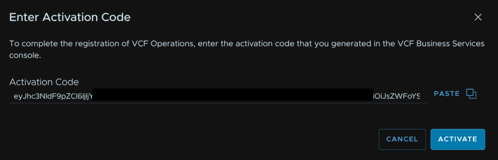
In VCF Operations click Start on Enter Activation Code
Paste the code in and click Activate
Now under Add Licenses To License Server, click Start
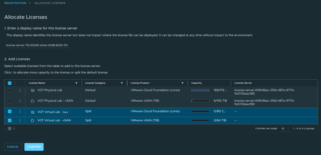
In the VCF portal, under Add Licenses, click Start
Select your licences and click Confirm
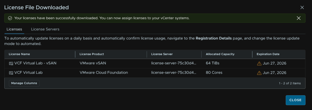
In VCF Operations, click Download
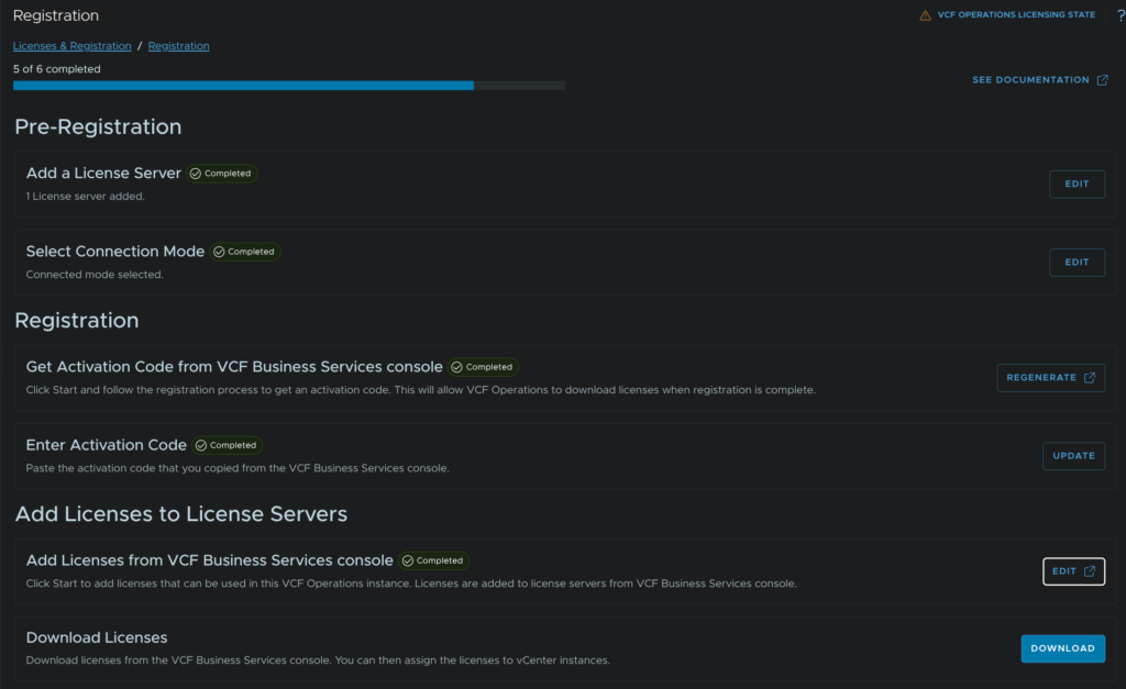
You should get a pop up, when thats come through, click Close
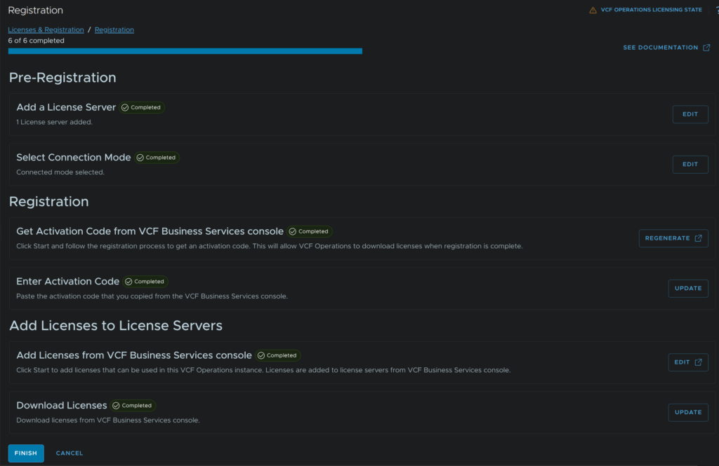
And click Finish
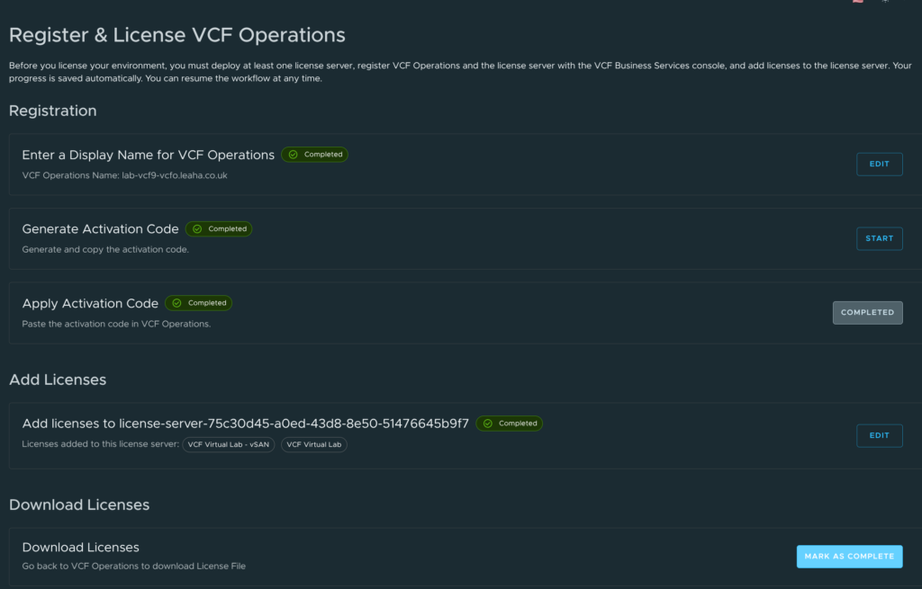
In the VCF Portal, click Mark As Completed
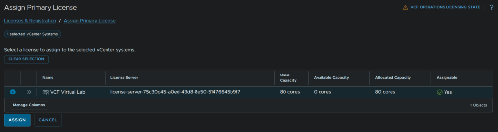
In VCF Operations, scroll down, select your vCenter and click Assign Primary License
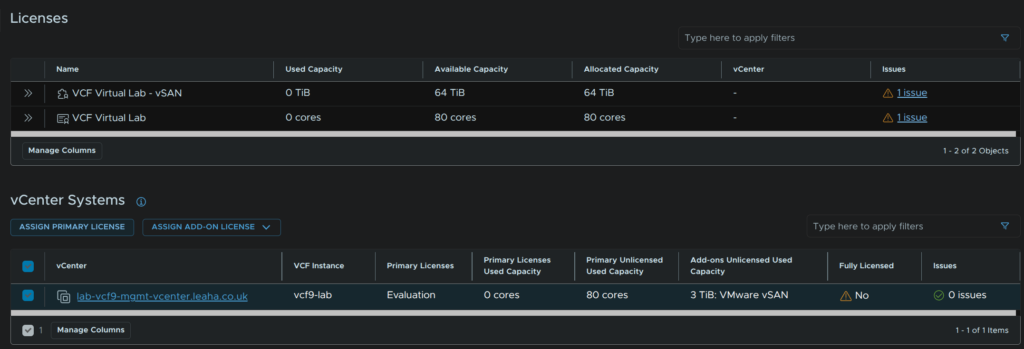
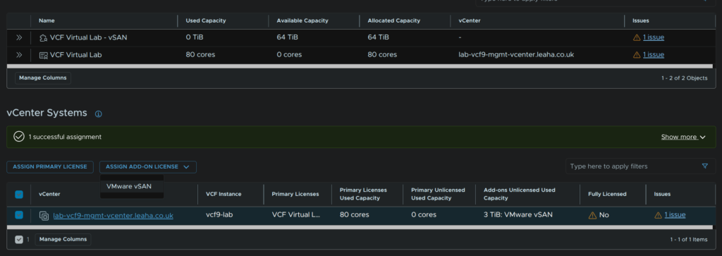
Select the license and click Assign
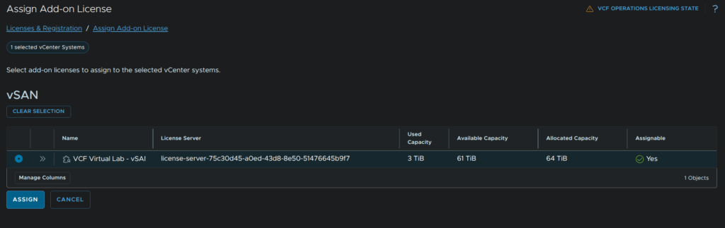
Repeat click Assign Addon License/VMware vSAN for vSAN
Select the license and click Assign
10 – Commissioning New Hosts
All hosts must be prepped like the management domain did in section 1 before you start
10.1 – Creating A Network Pool
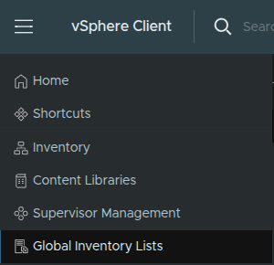
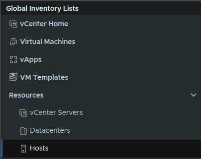
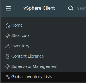
Open the management domain vCenter and click the three lines in the top left, then click Global Inventory Lists
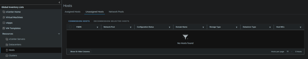
On the left, click Hosts
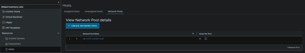
We first need a network pool, if you are expanding a cluster thats already been created, there will already be a pool that can be used, in that case you can skip this part, but if you are adding a workload domain a new pool will be required, for a new cluster you may or may not need a new pool
Pools must not have overlapping IP ranges
Click the Network Pools section and click Create Network Pool
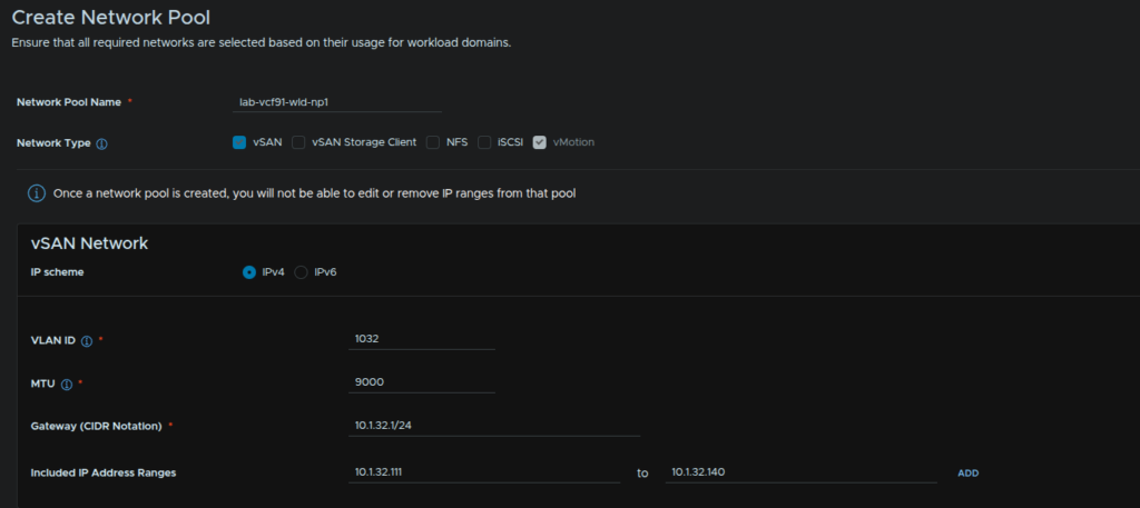
This part will depend on what you are deploying storage wise, but you’ll pool for vMotion and one for your storage, for this cluster I am using vSAN, it also needs a name
Hosts will also need to be setup like in the ESX section
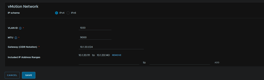
When you have your networks enter the VLAN, MTU, which likely is 9000, but this will match what you did in the deployment, then add the gateway in CIDR notation, its worth noting here, neither of my networks actually have a gateway, then enter an IP range for hosts
When you have the address ranges, you’ll need to click Add
It should then look like this with the network range added
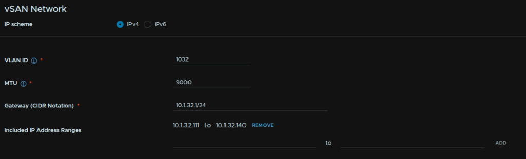
We then need to repeat for vMotion and click Save
10.2 – Commissioning New Hosts
Then we need to commission a host, in vSphere click the three lines in the top left and click Global Inventory Lists
Click Hosts/Unassigned Hosts/ click Commission Host
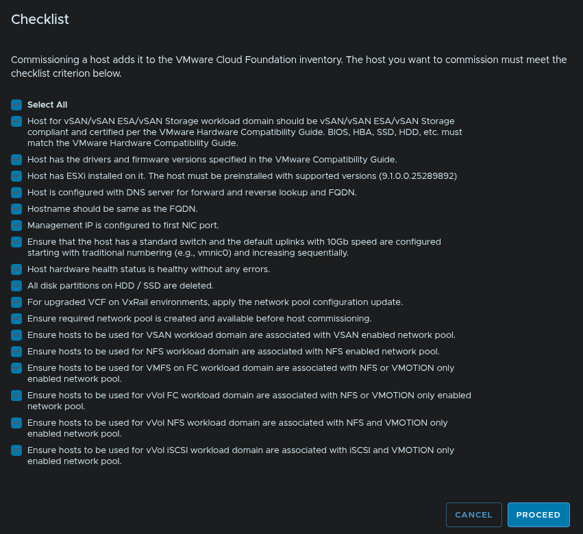
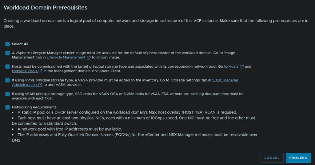
Check and prerequisites, you will need to select all before continuing
When you are happy click Proceed
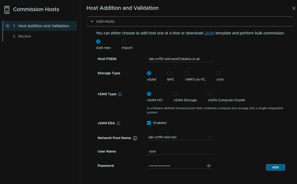
Add your host FQDN, select the storage type, select the network pool we created earlier, enter the root credentials and click Add
If your hostname is over 15 characters click Acknowledge, this can be ignored as hosts shouldnt be domain joined
Repeat for all hosts to commission, a non vSAN cluster requires at least two hosts, while vSAN requires at least three hosts, though I recommend four
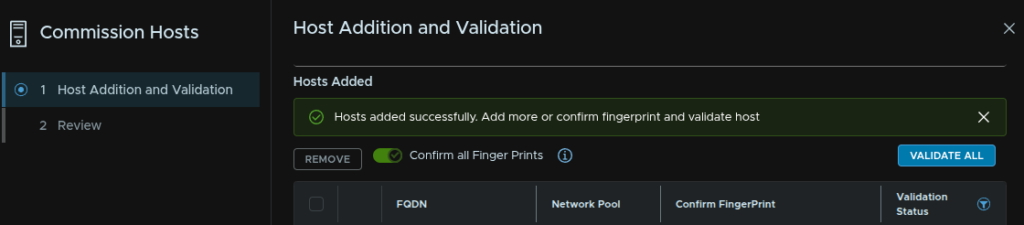
At the bottom, click the toggle to confirm the fingerprint and click Validate All
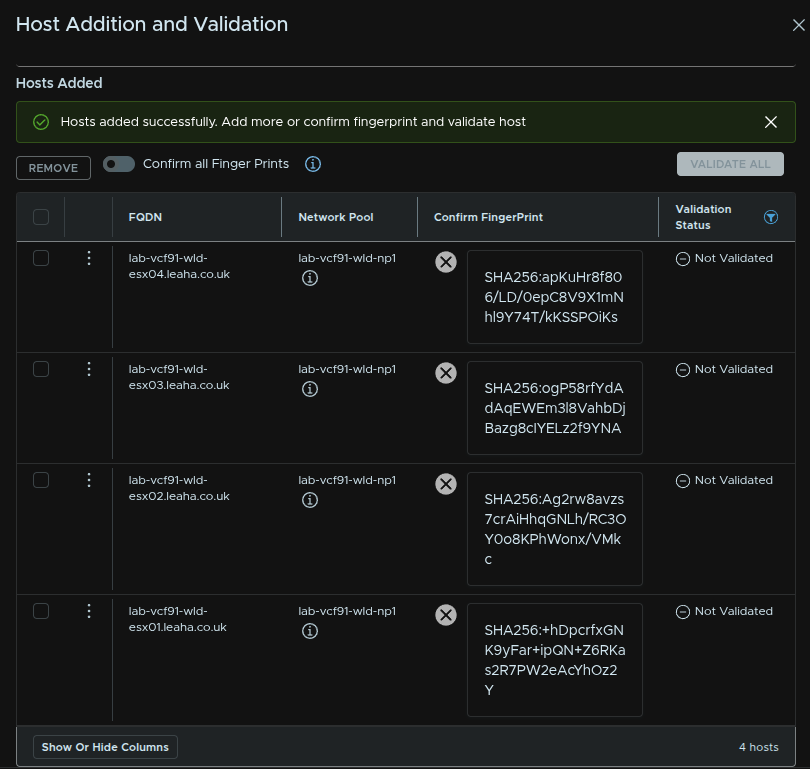
Then click Validate All
Once thats validated, click Next
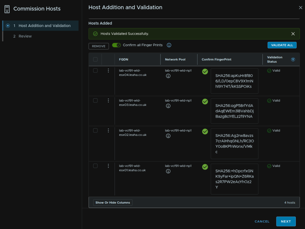
Then click Commission
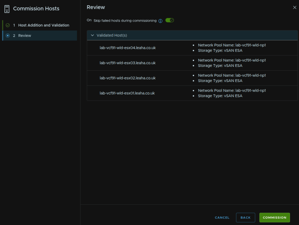
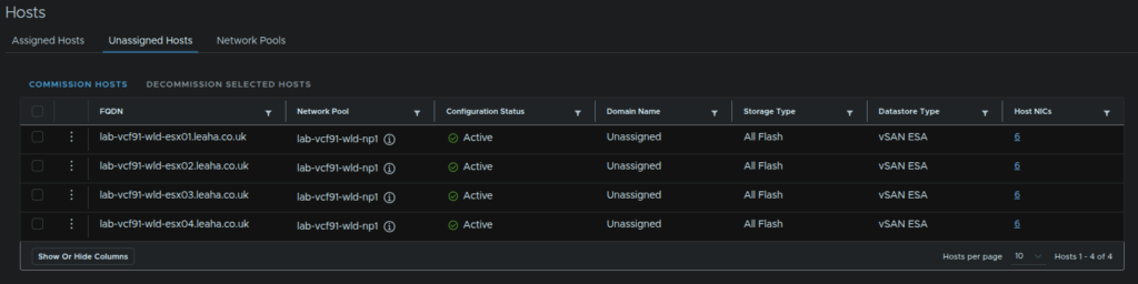
When its done it should look like this
11 – Importing An Image
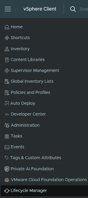
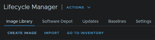
We first need an image for our new hosts, in the management domain vCenter, click the three lines in the top left and click Lifecycle Manager
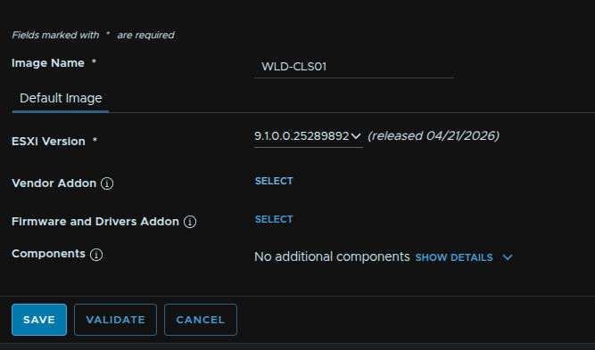
Click Create Image
Give it a name and select the release matching the ESX hosts current version
Then on vendor addon, click Select
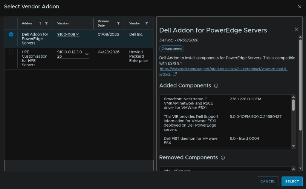
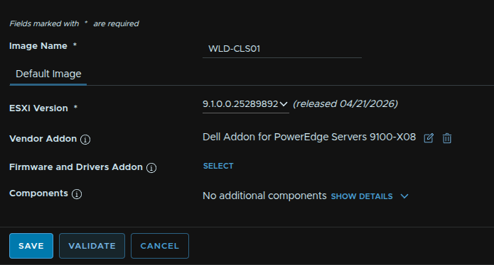
We have the following for Dell and HPE, when you have the one you want, click Select
You can also add addition components if you need, like GPU drivers, they will need manually uploading to the lifecycle manager
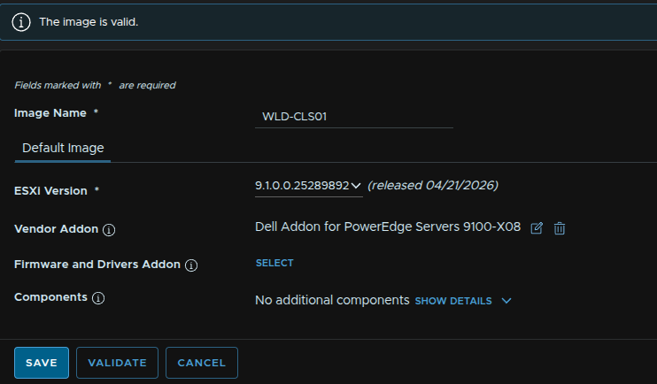
When you are happy, click Validate and when its valid
You may get an error if this matches the management domain image, if you have this skip this step
We can ignore the warning in the case and click Save
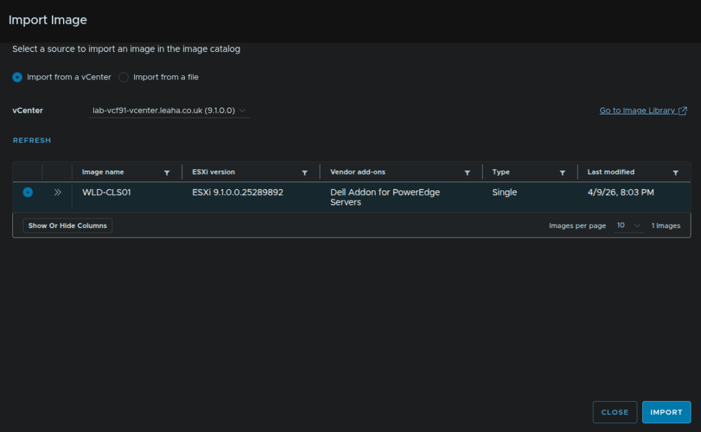
Now in VCF Operations, click Build/Lifecycle, expand VCF Instances, select your VCF Instance and click Image Management/Import Image
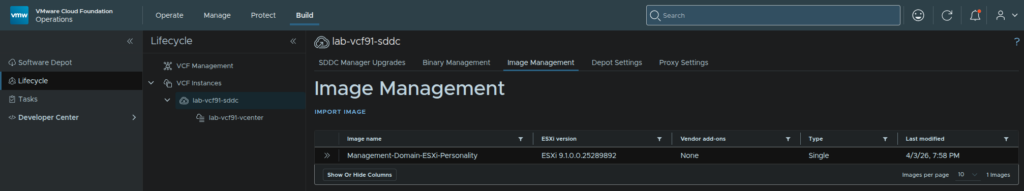
The vCenter should be auto populated as the management domain vCenter, then click the image and click Import
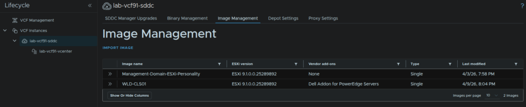
When its done you’ll need to refresh your page and you’ll see the image in there
12 – Deploying A Workload Domain
We will need the hosts making up our initial cluster to be added like in section 10
12.1 – Starting The Workflow
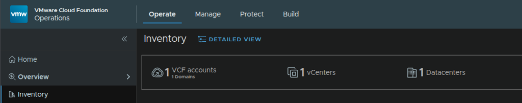
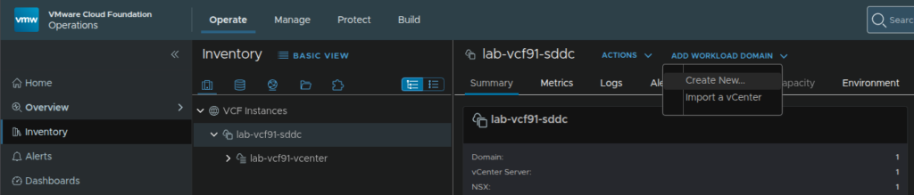
This will need to be done via VCF Operations, click Operate/Inventory, by default you will be on the simplified view, so click Details View
Expand VCF Instances and select your VCF instance, then click Add Workload Domain/Create New
Check the prerequisites and click Proceed
12.2 – General Information
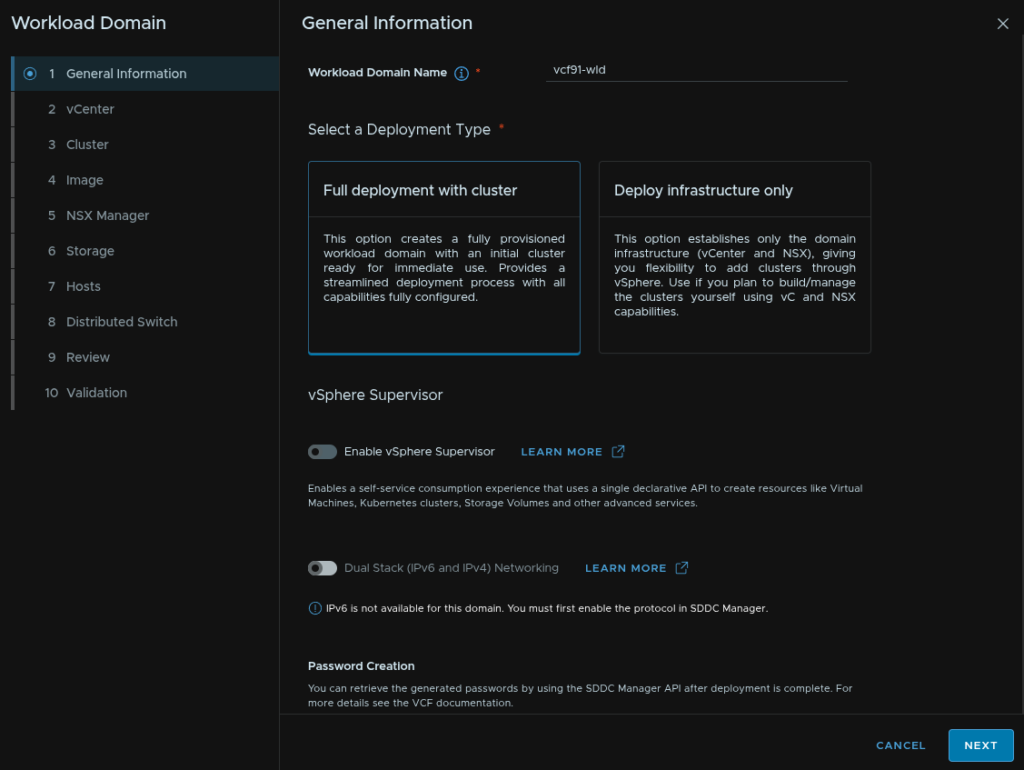
Give the workload domain a name and select Full Deployment With Cluster
We can disable the supervisor for now, it can be manually configured later like in section 7, credentials will be automatically generated and can be extracted after the domain has been built from the Operations UI, click Next
12.3 – vCenter
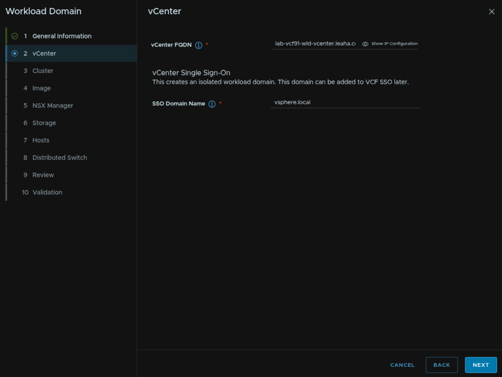
Add the vCenter FQDN, this will need to be on the same network as the management domain vCenter, enter an SSO domain fort he vCenter, the default vsphere.lcoal wil be fine then click Next
This will default to a large vCenter with 8vCPU and 30GB RAM
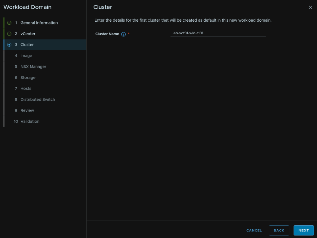
12.4 – Cluster
Give the cluster a name and click Next
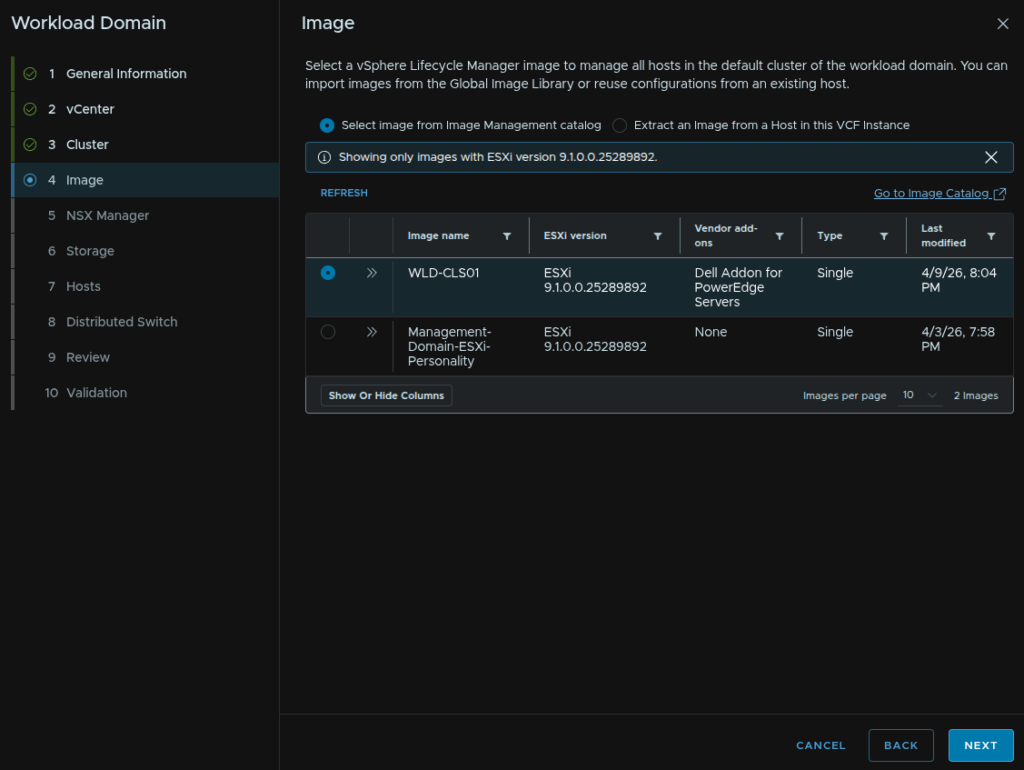
12.5 – Image
Select our new cluster image and click Next
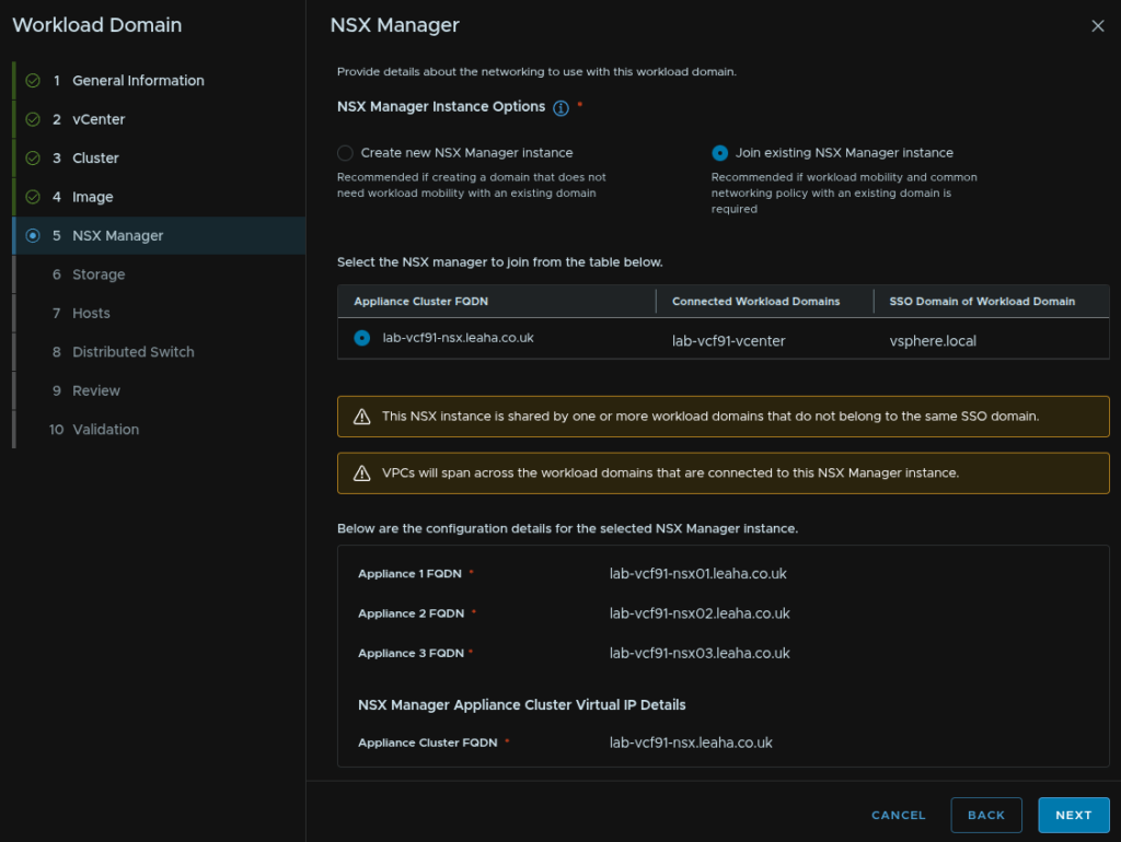
12.6 – NSX Manager
We then need to setup our NSX instance, I would always recommend HA in production
We get a couple of options, in VCF 9.1 we no longer require a dedicated NSX instance for the first workload domain and we now have the option of joining this to the management domain NSX instance
There are a few of things to note here
Firstly, you likely deployed the medium size for NSX during the deployment, this only supports two vCenters and I cant find the correct way, if possible, to scale this up
Secondly, everything in NSX will generally be available across domains, some people prefer separation, in which case we would want a dedicated NSX instance, though we can use the new Spans features to localize VPCs to particular domains
Thirdly, if you reuse a given NSX instance, the hosts will need access to the TEP VLAN the NSX is configured to use
If you are only deploying a single workload domain, this easily fits into the management domain NSX instance, so I would use this, it will save a lot of resources, if you are planning many workload domains, deploying a dedicated NSX instance here makes more sense, and then using the large size to accommodate up to 16 vCenters
If you deploy a new NSX instance you will need a VIP FQDN plus three more, one for each node and these will need to be on the same VLAN as the management domain vCenter
| Medium | Large | |
| Host Maximum | 128 | 1,024 |
| vCPU | 6 | 12 |
| RAM | 24 | 48 |
| Maxium Compute Managers | 2 | 16 |
I will be adding my instance to my existing NSX manager as I have a single workload domain and this is more resource efficient, if I need to isolate VPCs I can use the Spans feature
Select the Join Existing NSX Manager Instance and select the NSX instance, then click Next
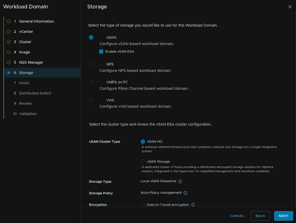
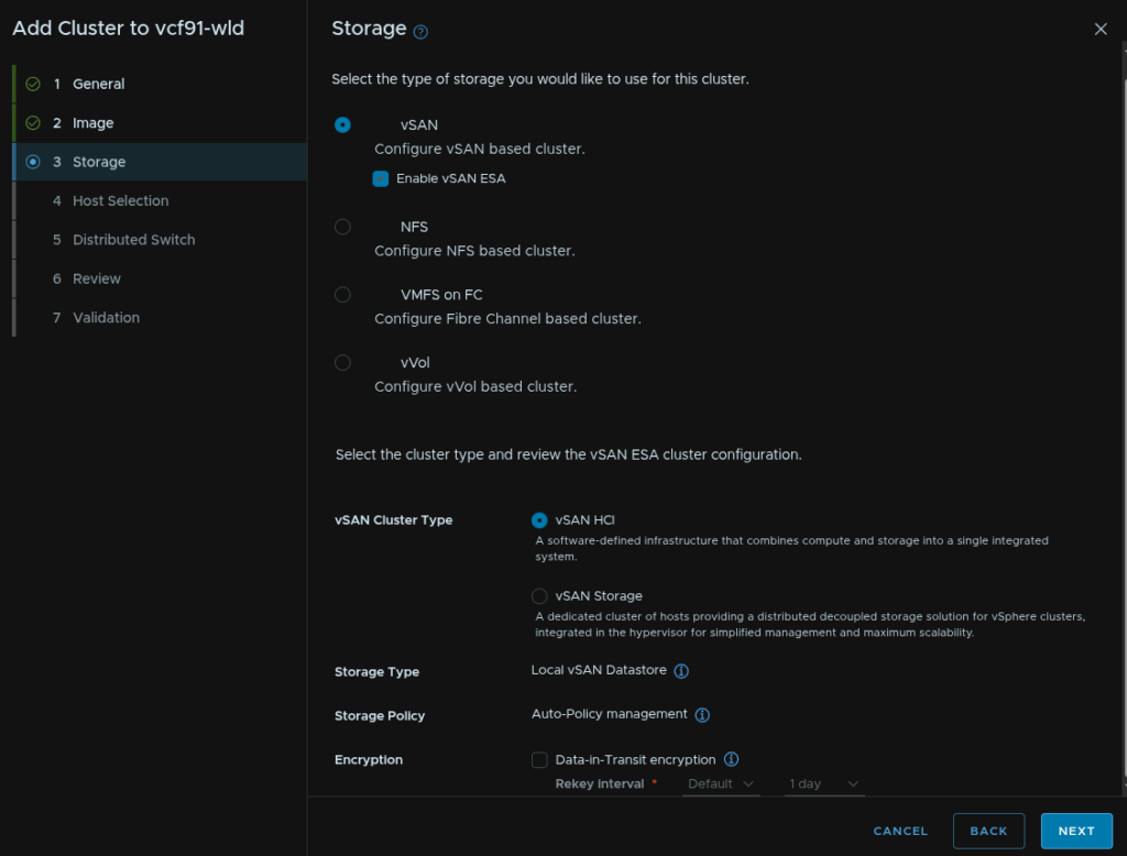
12.7 – Storage
We then need to choose our storage type, I have planned for vSAN ESA, so I select that and clicked Next
For vSAN, the default vSAN HCI is what you likely want, if you are unsure use this option, if you know you need a vSAN storage cluster select that and click Next
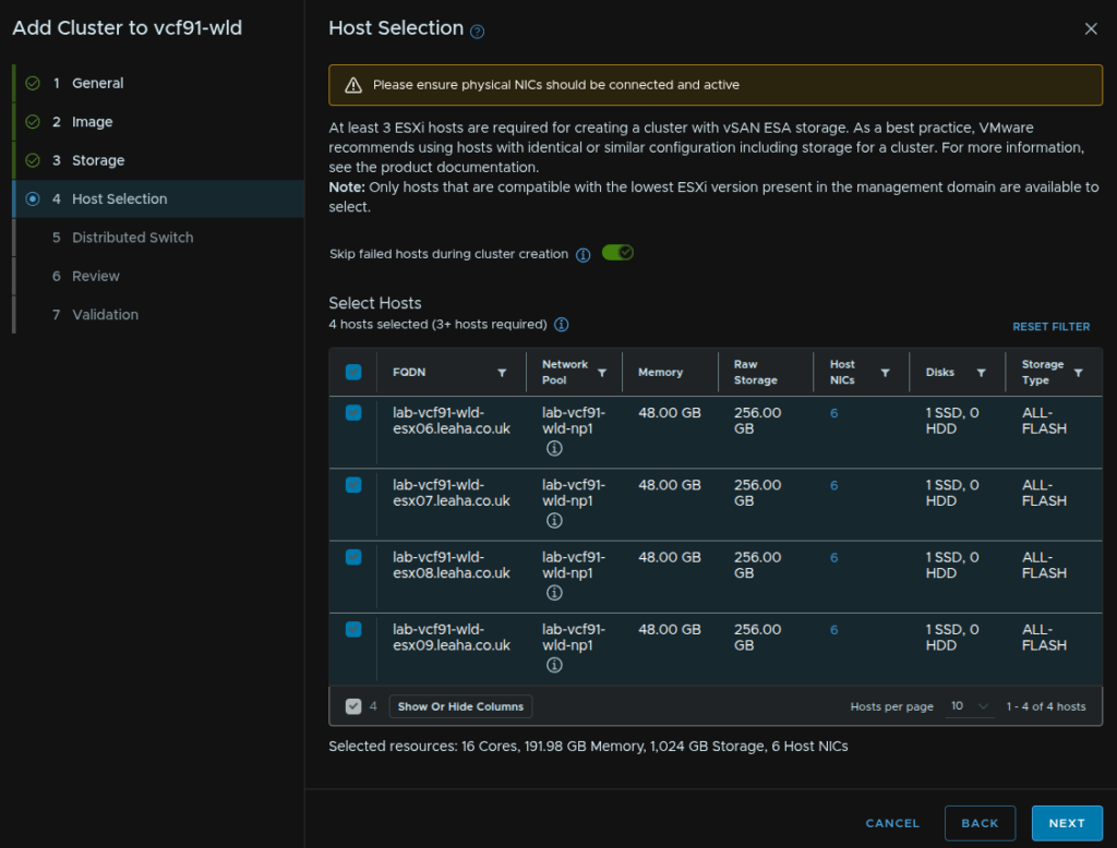
12.8 – Hosts
We then need to select our hosts, I am using all four I added earlier, then click Next
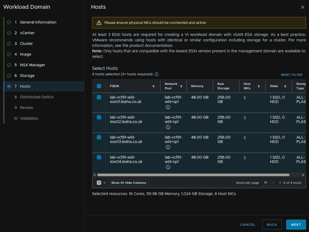
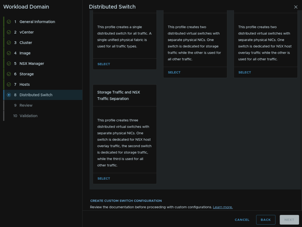
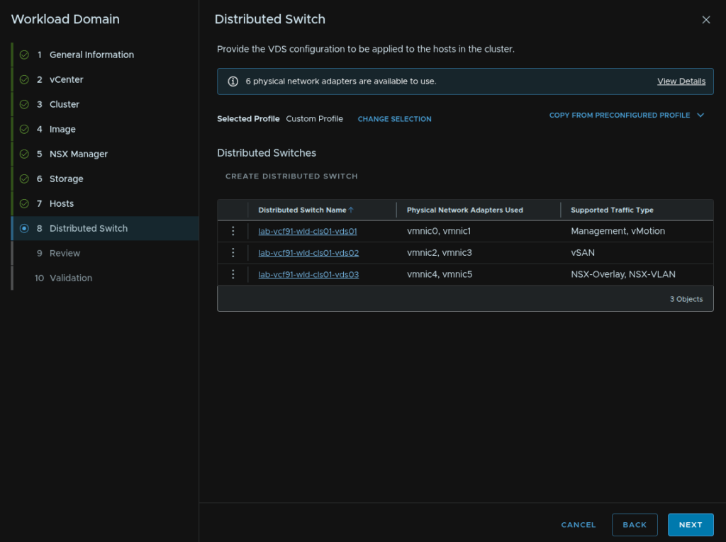
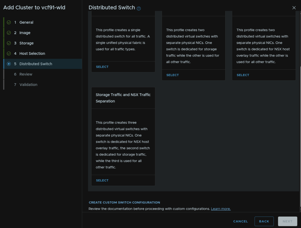
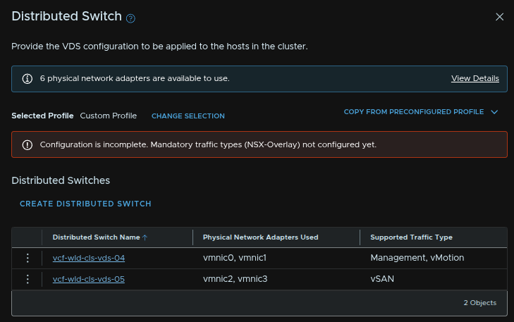
12.9 – Distributed Switches
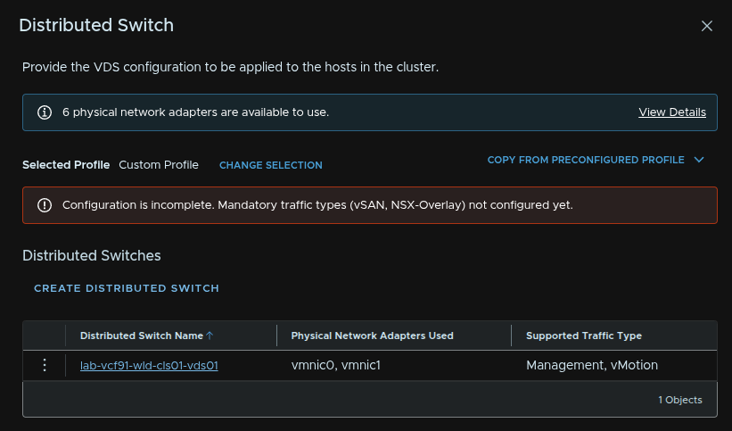
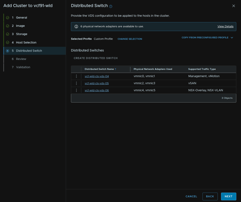
We then need to select our networking topology, I recommend 6 NICs using the storage and NSX traffic separation, but if you have only 4 NICs, what I would consider to be the minimum, use storage separation
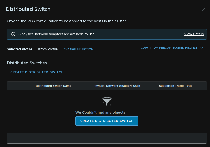
Now, while we have the defaults, this doesnt actually let you edit the settings, and the issue there is the NSX TEP addresses will be using DHCP when we want an IP pool like the management domain during the deployment, so click Create Custom Switch Configuration at the bottom, and we will manually set up the topology
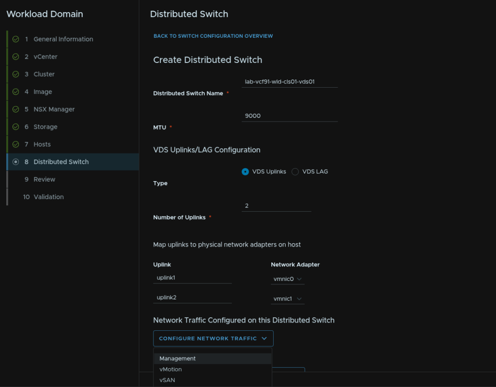
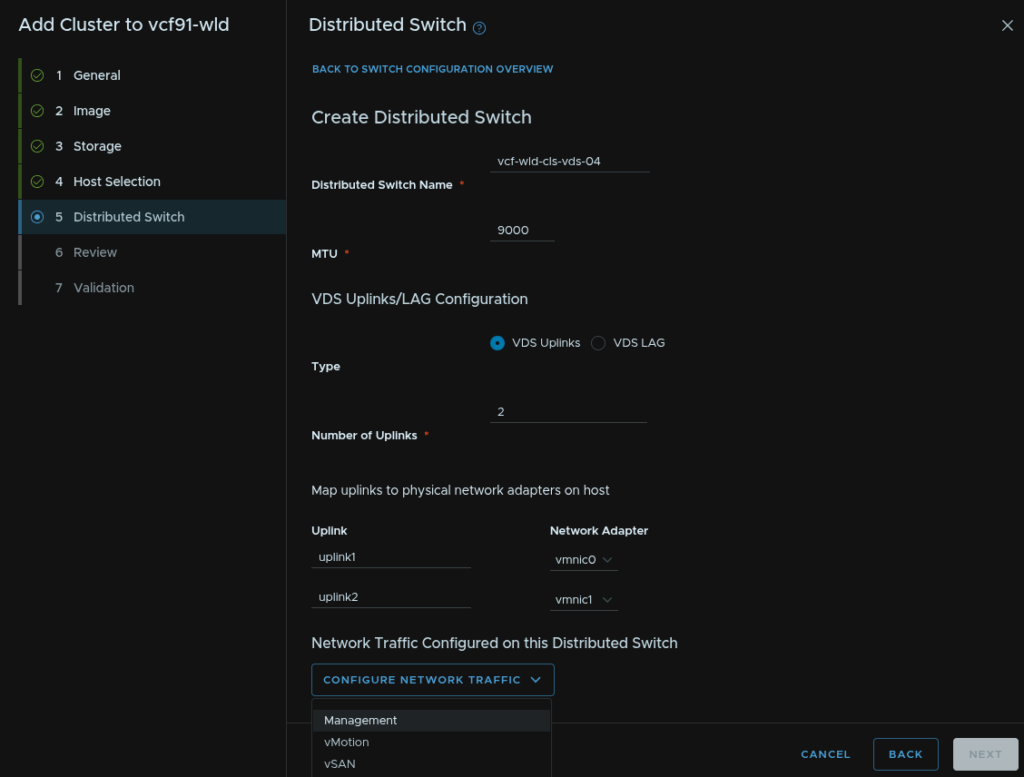
Click Create Distributed Switch

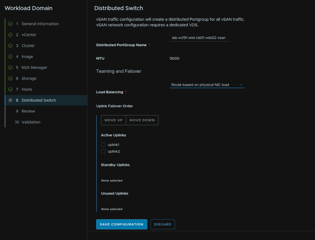
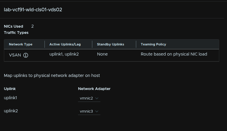
Add a VDS name and set the MTU, this should be 9000, but in line with what was set for the management domain, for Type, I would use VDS Uplinks, we need 2 uplinks, select the vmnics you want to use then click Configure Network Traffic Type/Management
One of these uplinks should be bound to the vSwitch on the default ESX install
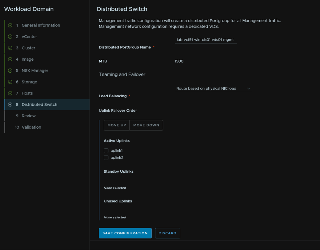
Give the port group a name and select the load balancing policy of route based on physical NIC load then click Save Configuration
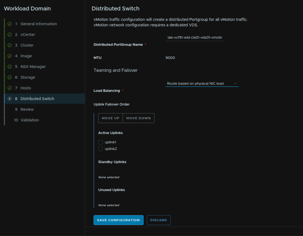
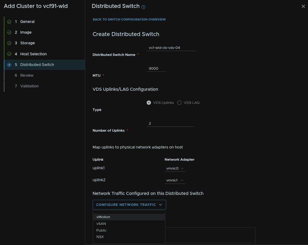
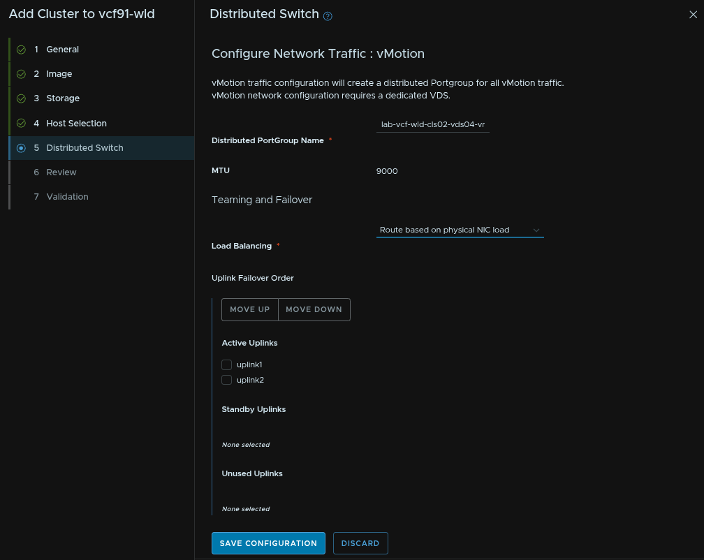
Click Configure Network Traffic/vMotion
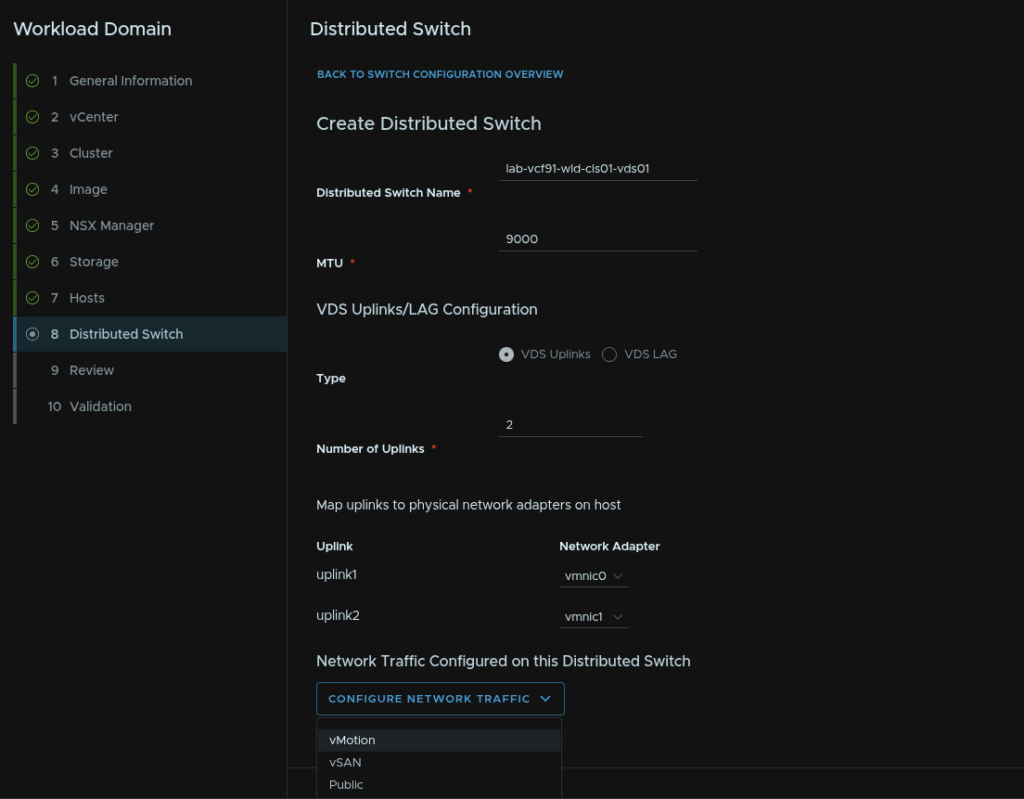
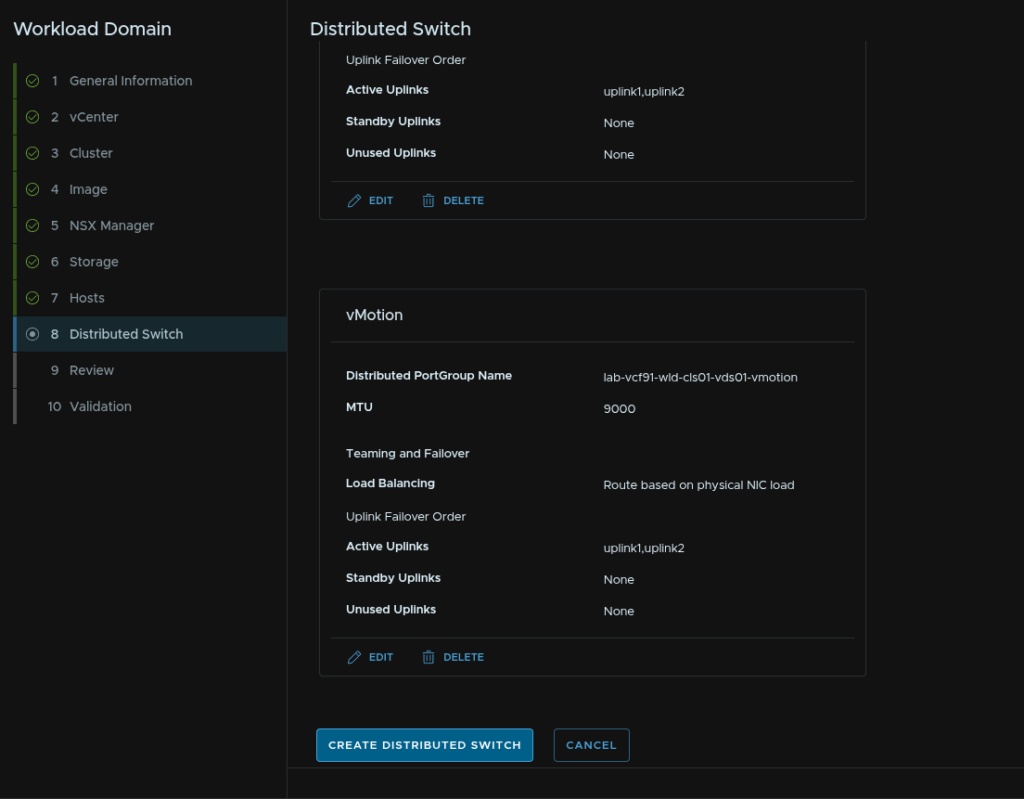
Give the port group a name and select the load balancing policy of route based on physical NIC load then click Save Configuration
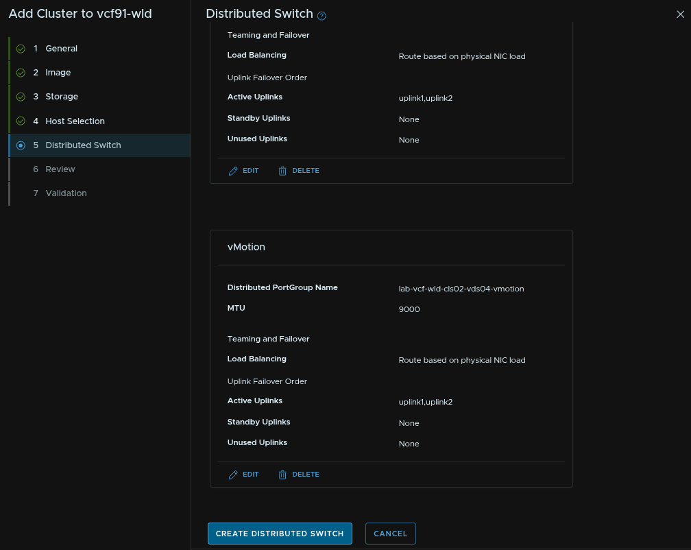
Scroll to the bottom and click Create Distributed Switch
Click Create Distributed Switch
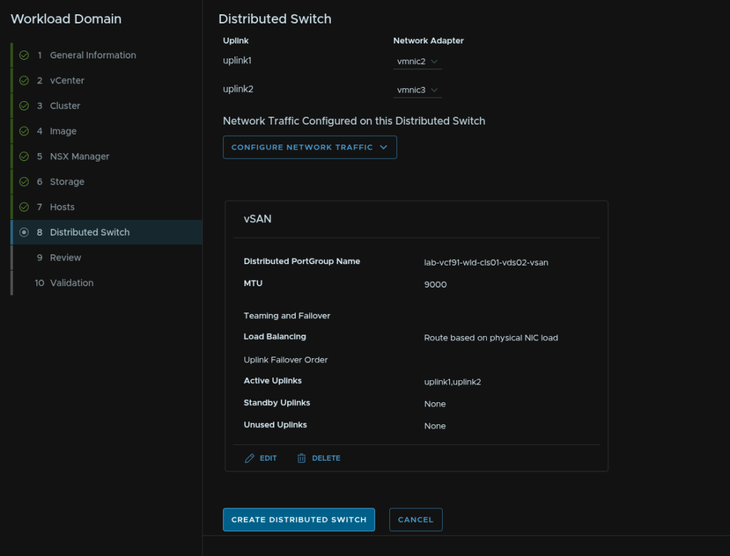
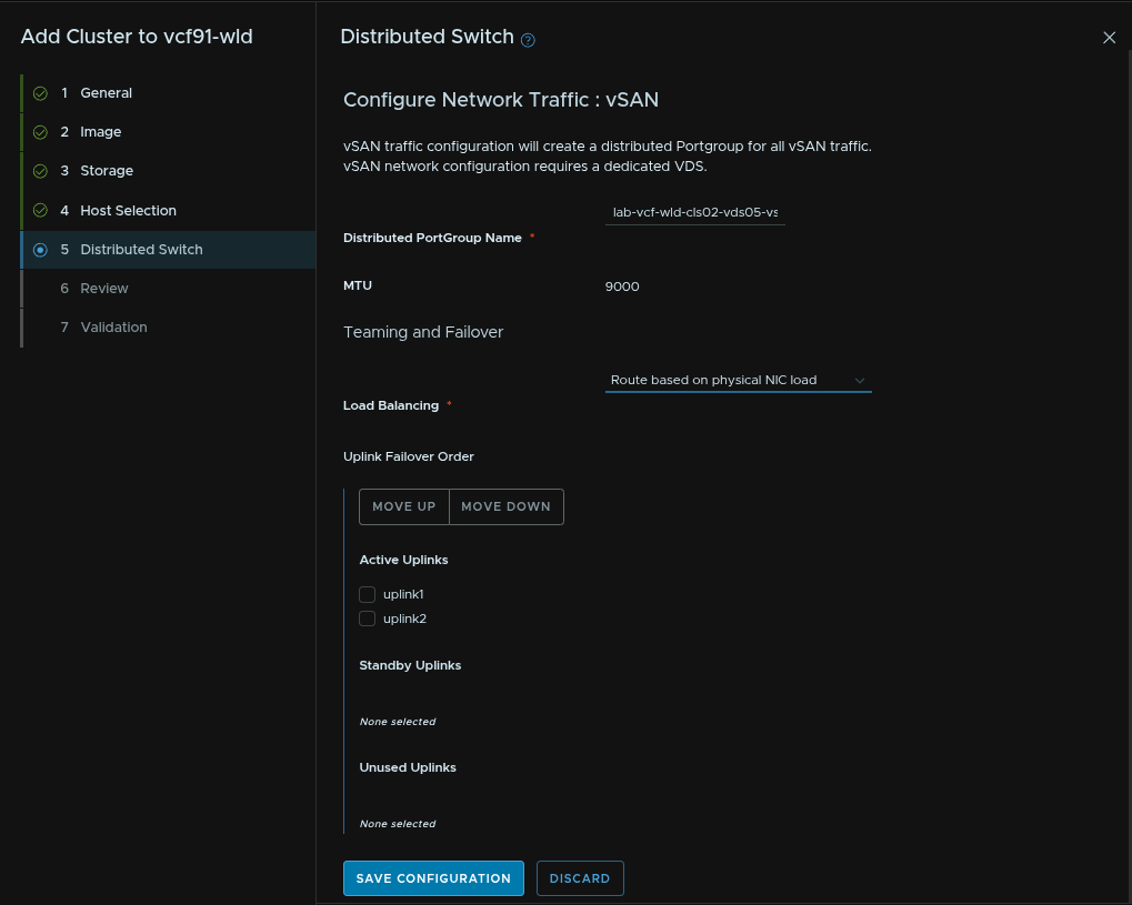
Give the VDS a name, set the MTU the same, which should be 9000, for the Type I recommend VDS Uplink, select the two uplinks you want to bind for storage and click Configure Network Traffic/vSAN
If you chose NFS configure that here

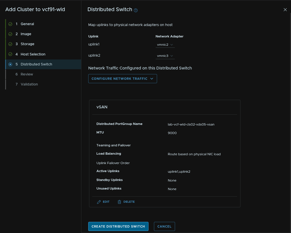
Give the port group a name and set the same load balancing option then click Save Configuration
Then scroll to the bottom and click Create Distributed Switch
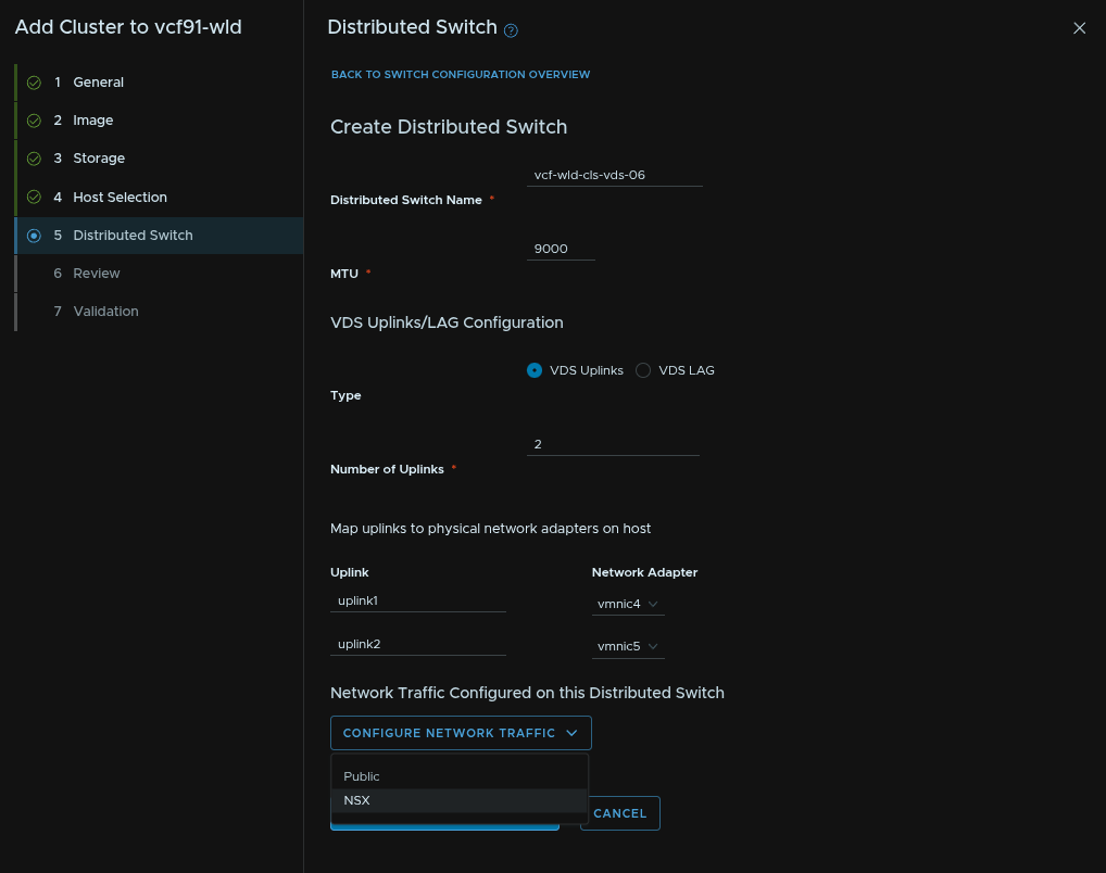
Click Create Distributed Switch one last time
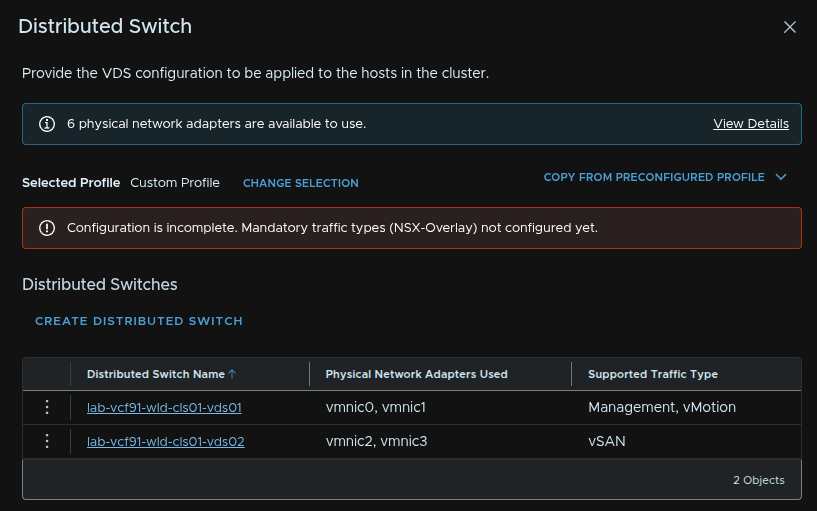
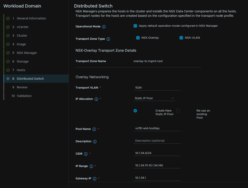
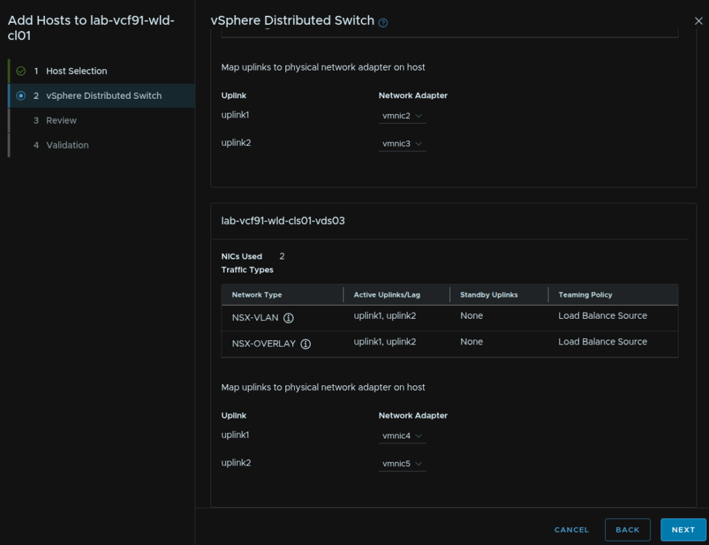
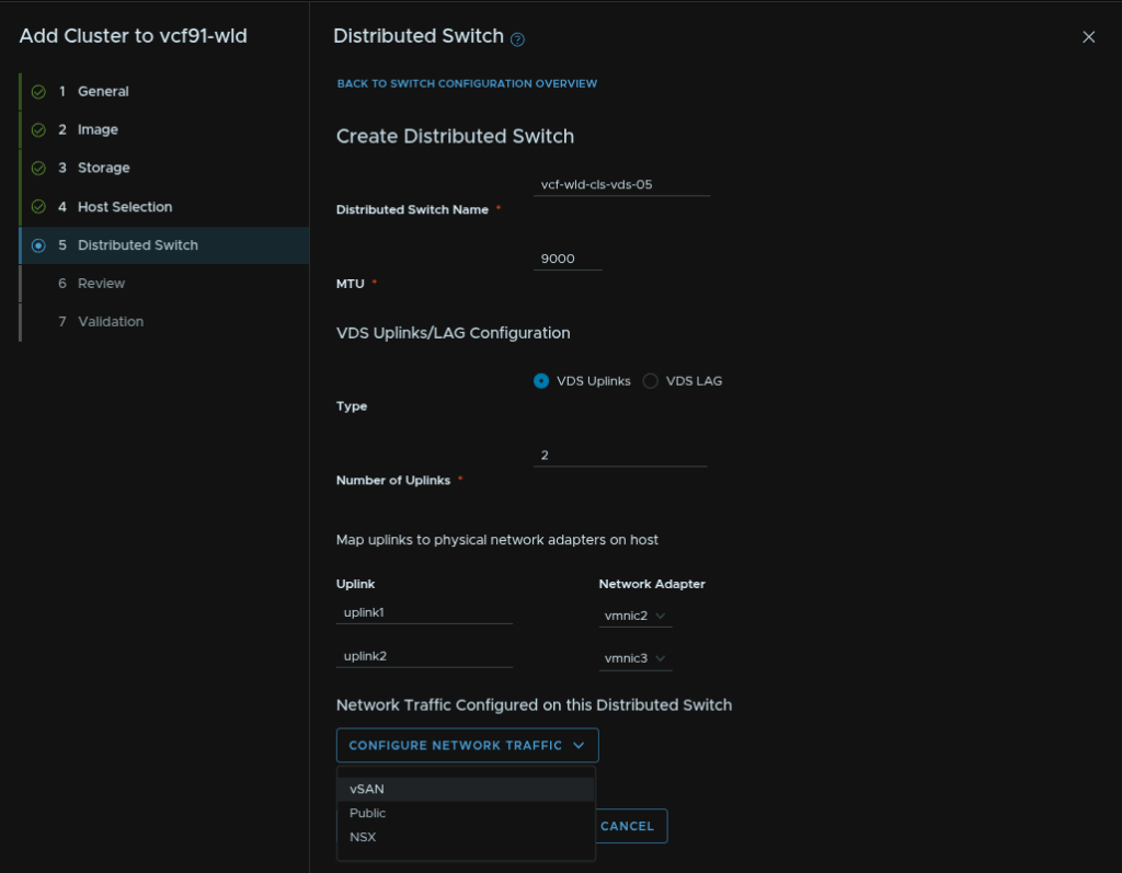
Give the VDS a name, set the MTU to the same, at 9000, for the Type I recommend VDS Uplinks, then add the remaining uplinks, then click Configure Network Traffic/NSX
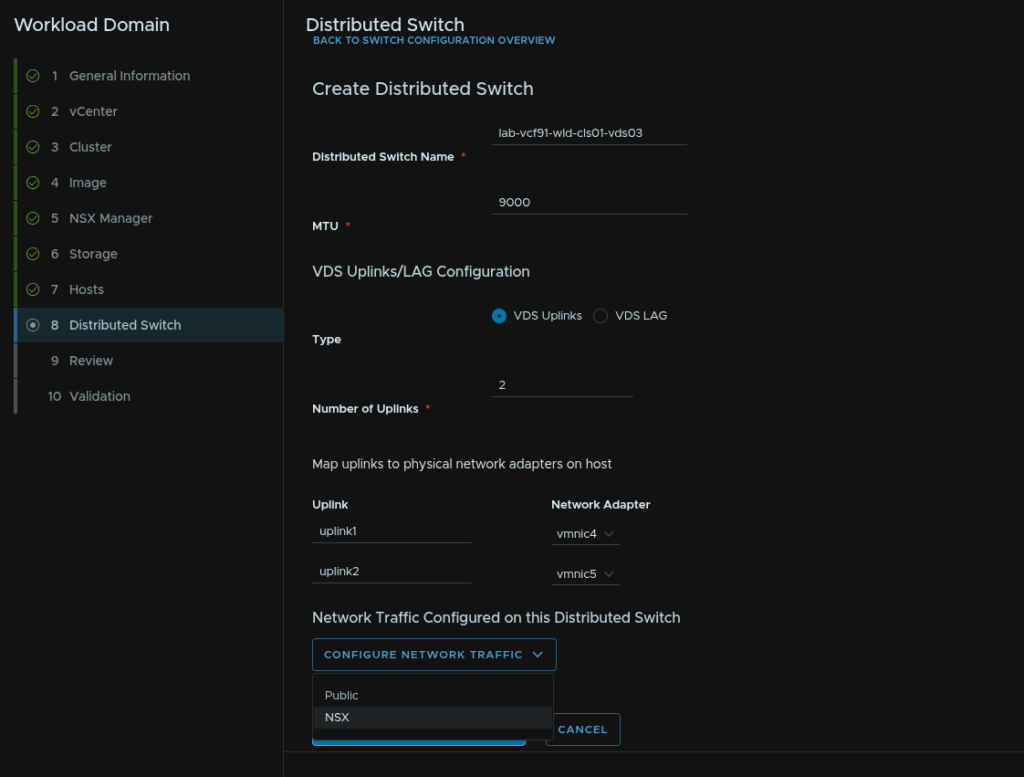
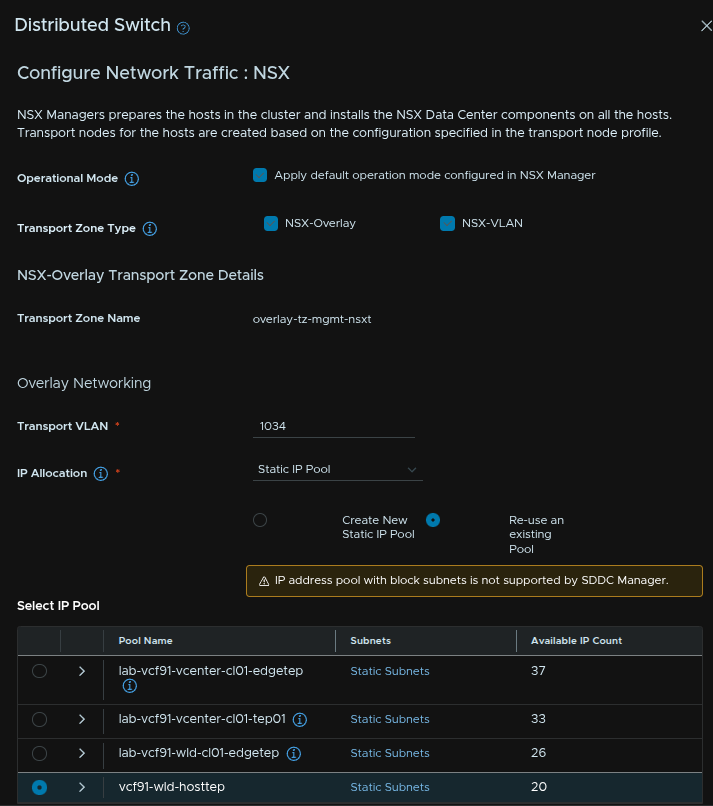
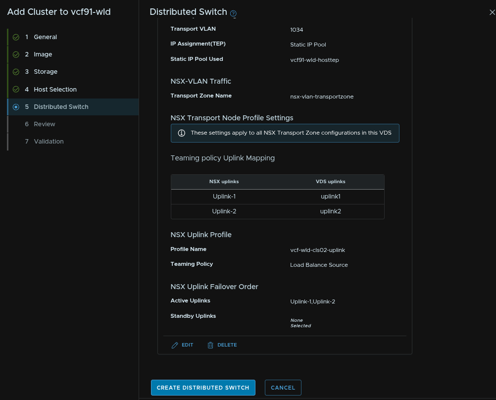
Leave the default boxes checked, all three should be, give the overlay transport zone a name, add the host TEP VLAN as the Transport VLAN, set the IP Allocation to Static IP Pool and create a new pool
Then give the pool a name, set the CIDR, IP range and gateway
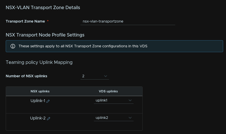
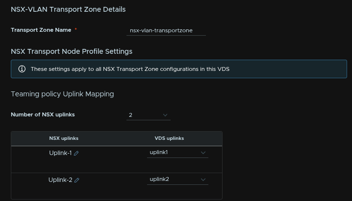
Give the VLAN transport zone a name, the uplink number should match the number on the VDS, in our case, 2, and set the NSX and VDS uplinks to match
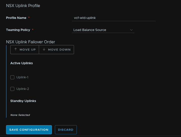
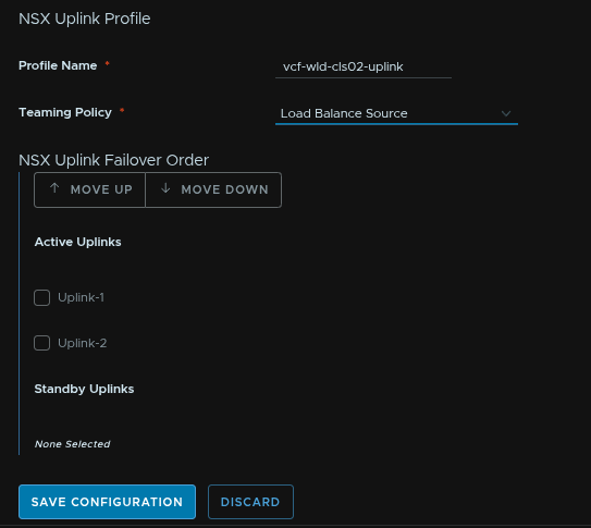
Give the NSX uplink profile a name and set the Teaming Policy to Load Balance Source and click Save Configuration
Scroll down and click Create Distributed Switch
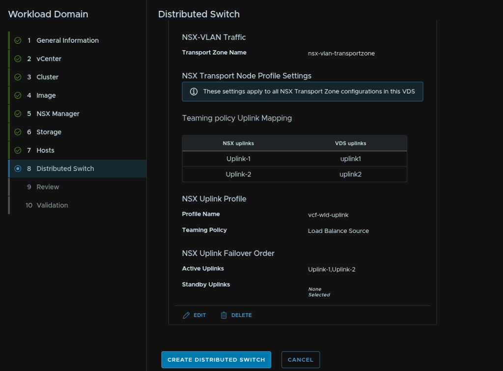
Then click Next
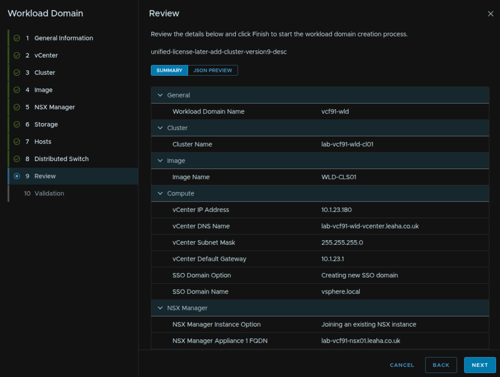
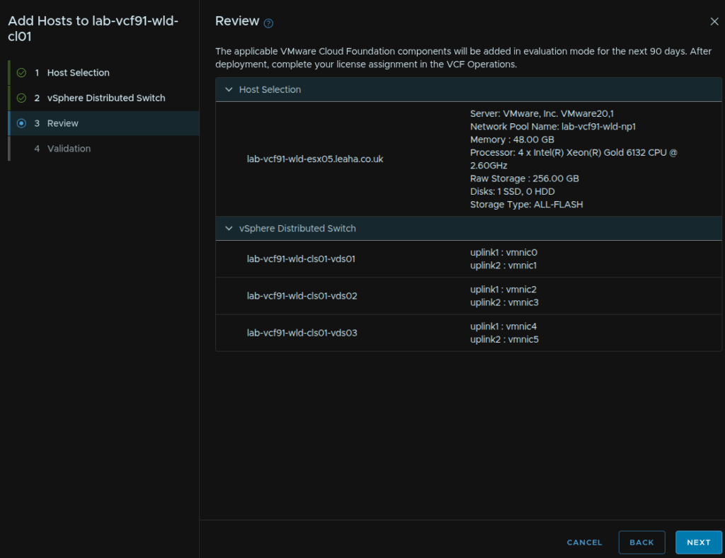
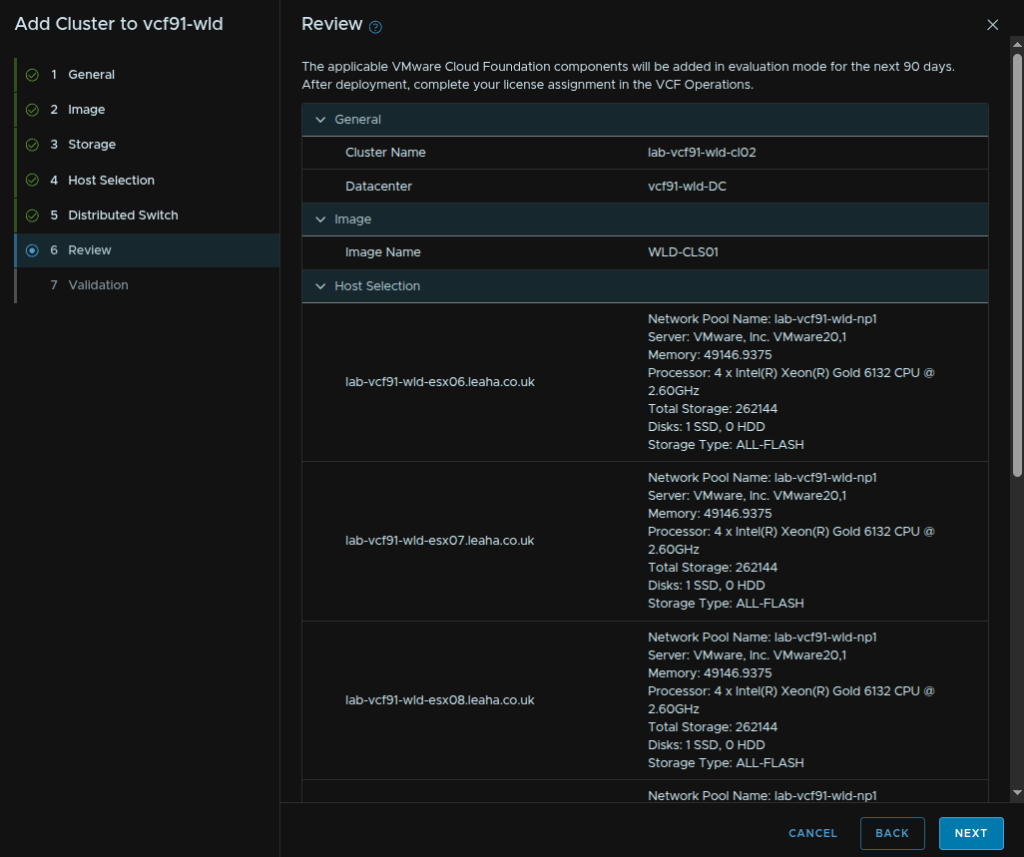
Review all the info and when you are happy click Finish
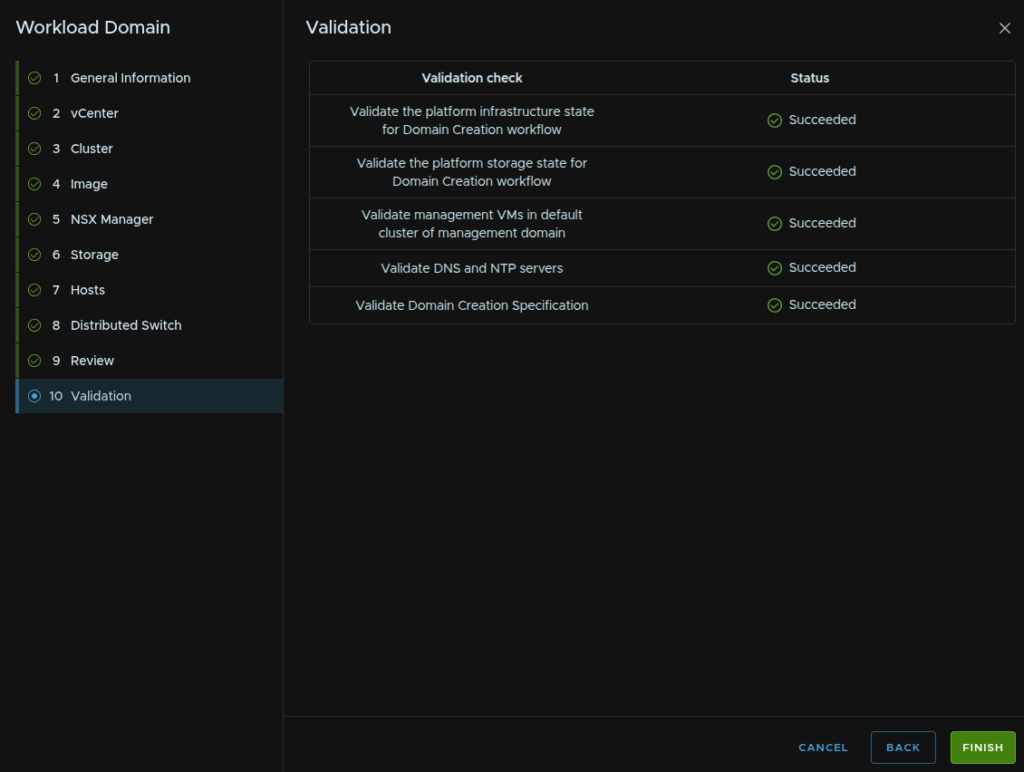
Once the validation has passed click Finish
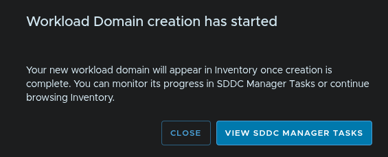
We can click View SDDC Manager Tasks on the pop up to track the progress
12.10 – Deploying A Cloud Proxy
Ideally, you want one collector/cloud proxy per domain, this isnt a hard rule, and it can be more efficient to reuse existing cloud proxies for data collection rather than deploying more increasing resource requirements
Here we will go through deploying a new proxy, if you wanted one, and in the next sub section, setting up the workload domain to use it
NSX and vCenter appliances are deployed into the management domain, and thats the bulk of the data we are collecting, and as such, the default workflow will also deploy the collector into the management domain, on the same network, so its as close to the data sources as possible#
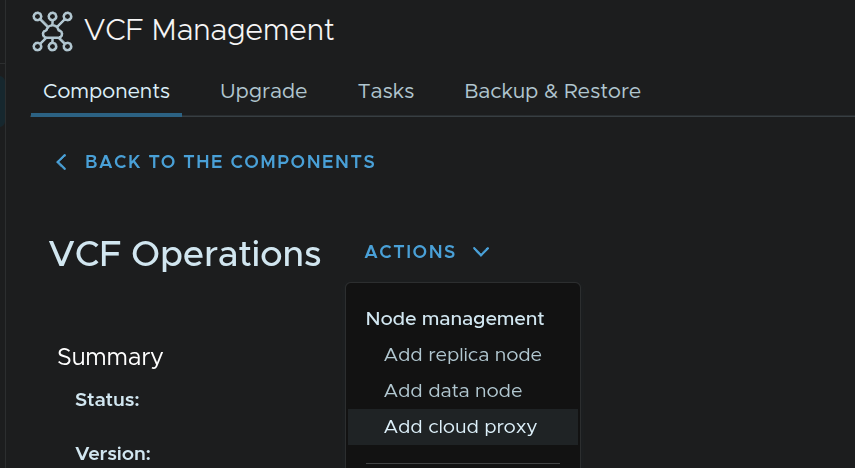
Log into VCF Operations and click Build/Lifecycle/VCF Management/Components and click VCF Operations
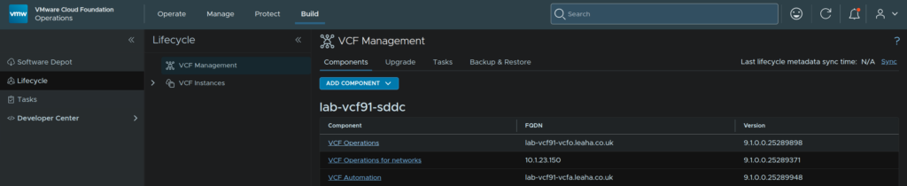
Click Actions/Add Cloud Proxy
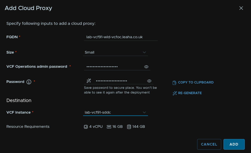
Enter an FQDN, this must be registered in DNS, select the size, Small will be fine for most scenarios, enter the VCF Operations password and click Re-Generate
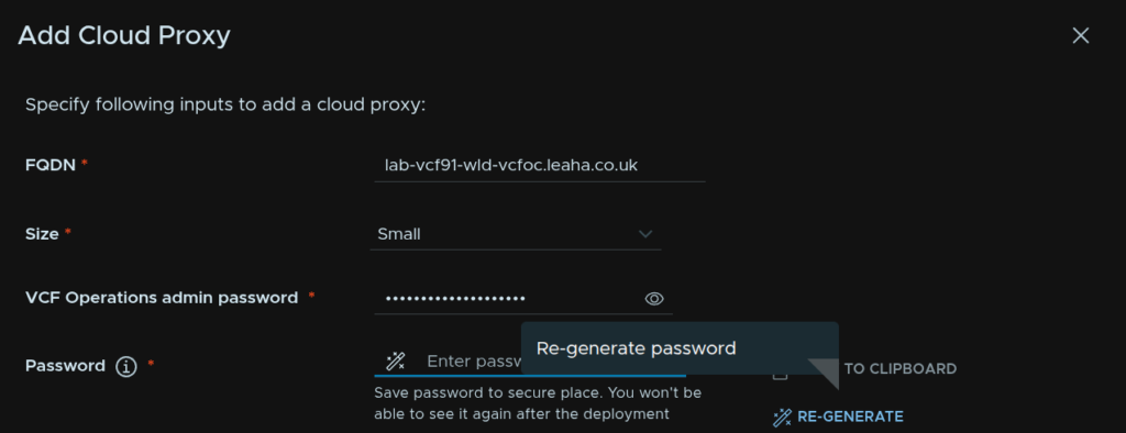
You can use the eye to see the password and save it, you wont be shown it again

Select our VCF instance and click Add
12.11 – Setting Up The Workload Domain Integration
By Default, the workload domain should get integrated after about an hour or so, but lets properly configure this with our new collector, Ops For Logs and Networks
In VCF Operations click Operate/Administration/Integrations, expand VMware Cloud Foundation, then click the three dots on your VCF Instance and click Edit
Make sure System Managed Credentials is checked, select our new workload domain collector, and make sure Operational Actions is enabled, then check Activate Log Collection and click the vSAN tab
Ensure its enabled and SMART data is being collected then click the NSX tab
Ensure NSX is activated, if you have Operations For Networks, also enable that, I didnt redeploy it when I rebuilt my lab, so I left it, then click Save in the bottom left
13 – Workload Domain NSX Networking
How we tackle workload domain networking depends entirely on how we setup NSX during the deployment, if we created a new NSX instance we can repeat the steps outlined in section 3
If you didnt, like me, and joined it to an existing NSX manager, we will want to create a new transit gateway, edge cluster, T0 gateway and connectivity profile
The reason for this is, if you dont, while VPCs will show in the workload domain, they are being routed by the management domain Edge cluster we deployed, if you have a dedicated 10Gb link between domains, its not a massive issue, but ideally we want a dedicated networking environment for this domain that uses local Edge nodes without routing between domains unless traffic needs to go there
By default, all VPCs will be visible across all domains, and for now we will leave it this way, so networking is accessible everywhere, as this may be required depending on what you are doing with it
When I get round to doing my NSX configuration guide we will cover spans and how we can use them to isolate VPCs to a certain domain/cluster
13.1 – Deploying The Edge Cluster
Before we can start, we need a new Edge cluster in the workload domain to keep all its networking local
We will also need two FQDNs registering on DNS, for the network, I will be using the same network as my ESX management, in a similar style to the management domain, but you can choose any port group in the workload domain, my ESX management VLAN in the workload domain is different from that of my management domain
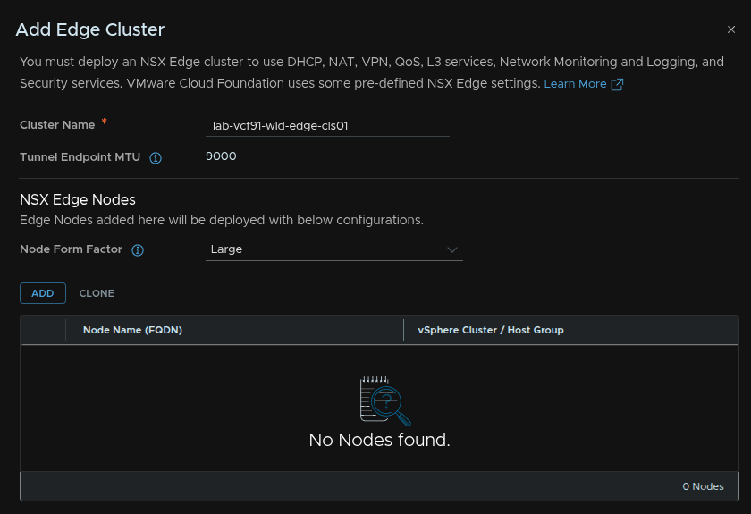
In the workload domain vCenter, click the vCenter object on the left, and click Configure/Networking/Edge Clusters/Add Cluster
Give the cluster a name and set the form factor to Large then click Add
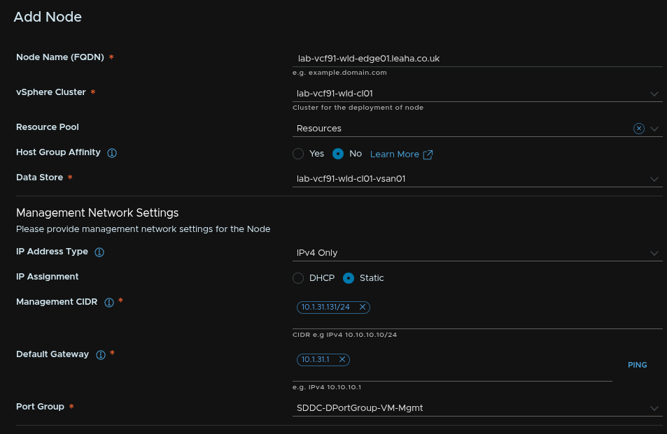
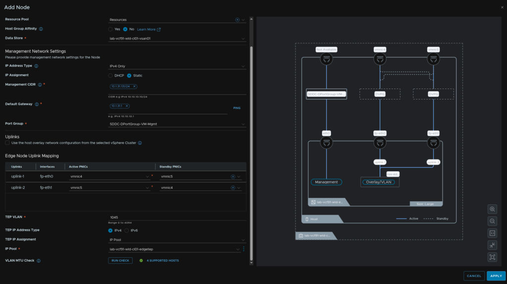
Enter the node FQDN, select the cluster, optionally add a resource pool, leave host affinity on No, we can configure this later, select a datastore
Then for the management IP select IPv4 only and click Static for the assignment, enter the management IP in CIDR address, add the gateway, then select the port group you want for management, you can use the ESX management one, but I recommend a dedicated port group on for VM Management, this should be ephemeral
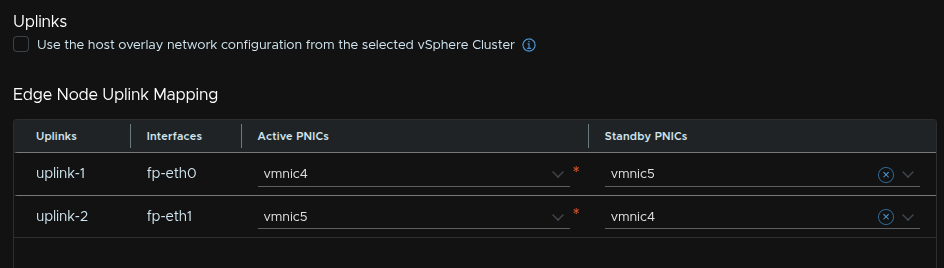
For the uplinks, uncheck the box to use the host overlay network the active/standby pNICs should alternate like this and will be populated by default
Enter the Edge TEP VLAN, for the IP Type, select IPv4, select IP pool, then click the three dots and click Create New
Give it a name and click Set under Subnets
Click Add Subnet/IP Ranges
Add an IP range for TEPs, then add the network in CIDR notification, gateway, DNS servers and DNS suffix then click Add
Then click Apply
Add a description and click Save
Now click Run Check to check the VLAN MTU
Then click Apply
And repeat for the second Edge Node, we wont need a new IP pool as we can select the new one from the drop down
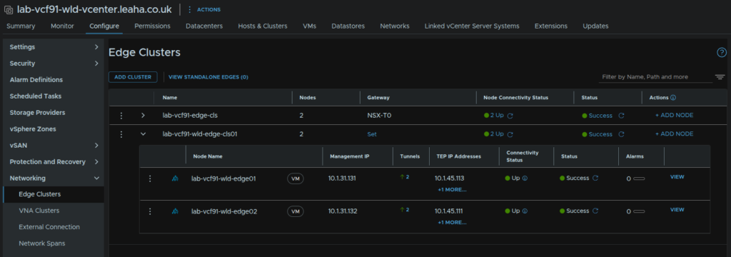
Once thats done it should look like this
At the bottom we can remove the toggle to set our own passwords if we want to, when you are happy, click Save
When its done it should look like this
13.2 – Creating The Uplink Segments
Before we can get our T0 gateway configured for external connectivity at the vCenter we need the uplink segments, and we need 4 to match the existing ones but for the uplink VLANs for our new workload domain
Open the NSX GUI at the VIP address and log in with admin account
Head to Networking/Connectivity/Segment Connectivity/Segments and click Add Segment
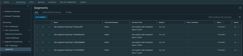
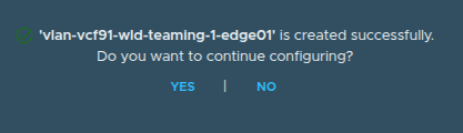
Give it a name, and select the same transport zone as the other segments, the nsx-system-vlan-transport-zone, add the VLAN tag for uplink 1 and select the pre created teaming-1 Uplink Teaming Policy and click Save
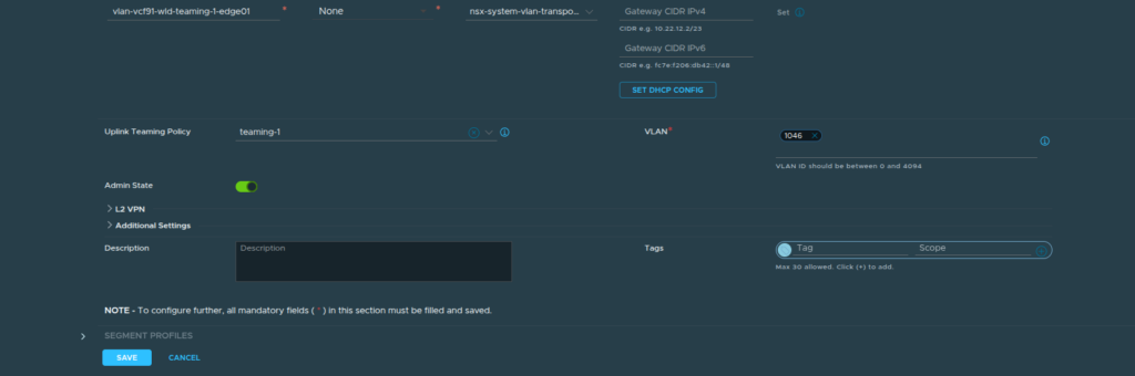
Click No here
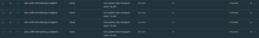
Repeat for three additional segments, 1 per edge per uplink VLAN
For the second VLAN, in my case 1047, use Teaming-2 like this
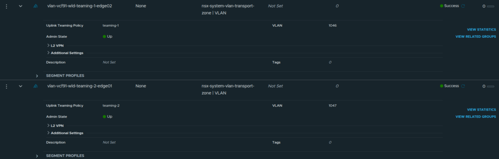
When your done it should look like this
13.3 – Creating A T0 Gateway
Now we have our cluster, we need a new T0 gateway, if we reuse the gateway from our initial deployment, then all traffic leaving NSX will go via our other domain, which we dont want
To do this, open the NSX GUI, on the VIP FQDN and log in with the admin account
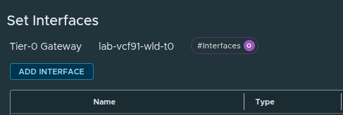
Click Networking/Connectivity/Tier-0 Gateways/Add Gateway/Tier-0
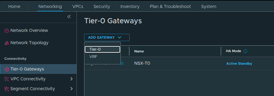
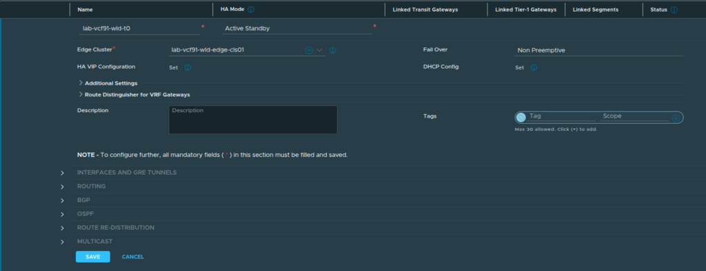
Enter a name, select the HA mode as Active/Standby, else NAT wont work causing issues with the Supervisor and K8S, select our new edge cluster and click Save
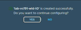
When you see this popup, click Yes, as we need to edit a few things
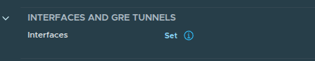
Expand Interfaces & GRE Tunnels and click Set
Click Add Interface
The first interface will be for the first edge on the first uplink VLAN, give it a name, add an IP in CIDR notation for that VLAN, in my case 1046, and select the segment for teaming-1 on that VLAN for edge01, then select the Edge Node, and click Save
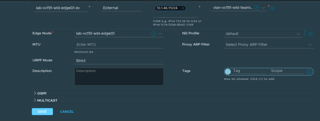
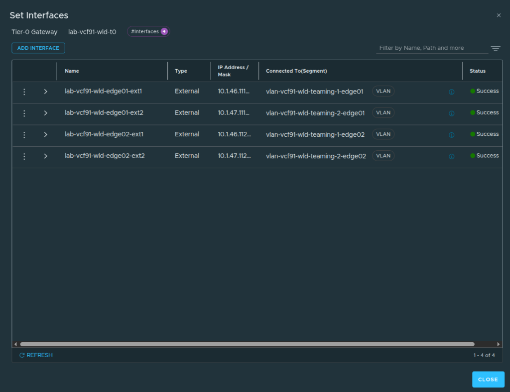
We then need to repeat for all Edge nodes so that there is 1 interface per segment, one per VLAN per Edge
You should get something like this, click Close
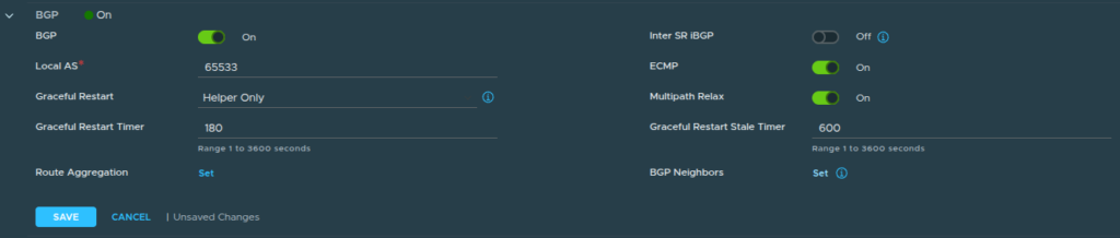
Now for BGP, like before, this depends on how you have it setup, but we will be using the same concept as the management domain with a local AS number unique to this cluster, going over two BGP VLANs, which each of your ToR switches would own one each
This will not cover the BGP side outside of NSX
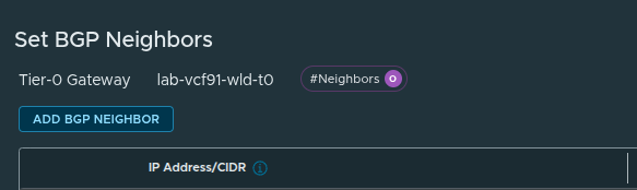
Expand BGP and set the local AS number, and by BGP neighbors on the right, click Set
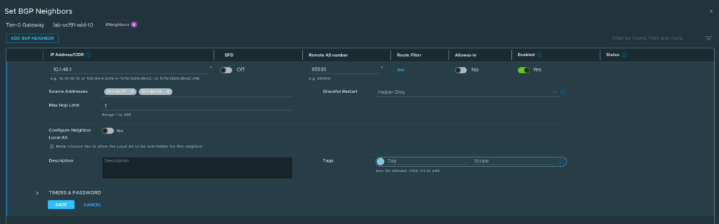
Click Add BGP Neighbor
Add the BGP peer IP and remote AS number, then add the source addresses from the drop down that match the subnet and click Save
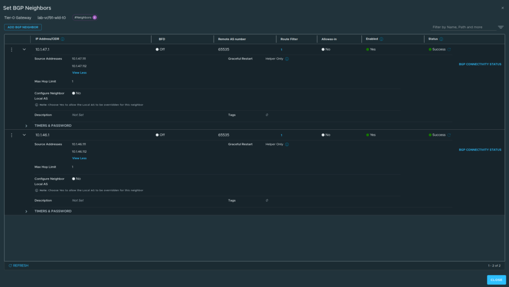
Then repeat for the other VLAN, your remote AS will likely be different for these peers, as mine is a single device for my lab, they ahev the same AS number
When you are done it should look like this, click Close
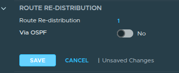
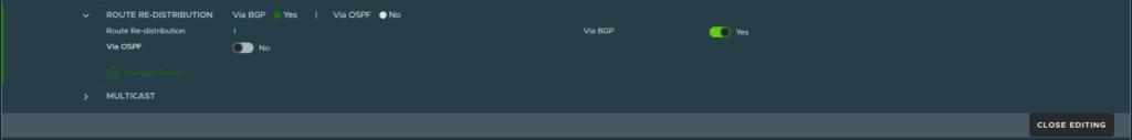
Now expand Route Redistribution and click Set
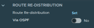
Click Add Route Redistribution
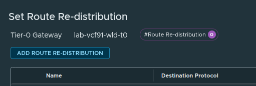
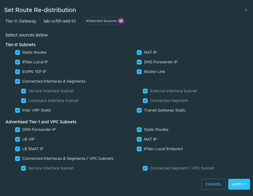
Click Set
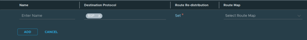
Check all boxes and click Apply
Then click Add
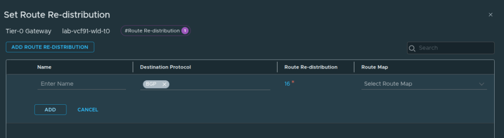
Click Apply
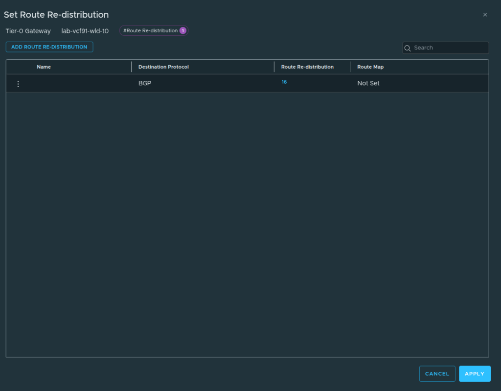
Click Save
Then click Close Editing
13.4 – Creating A New Transit Gateway
Now we have an edge cluster, we can create a new transit gateway and connectivity profile to utilize at our workload domain
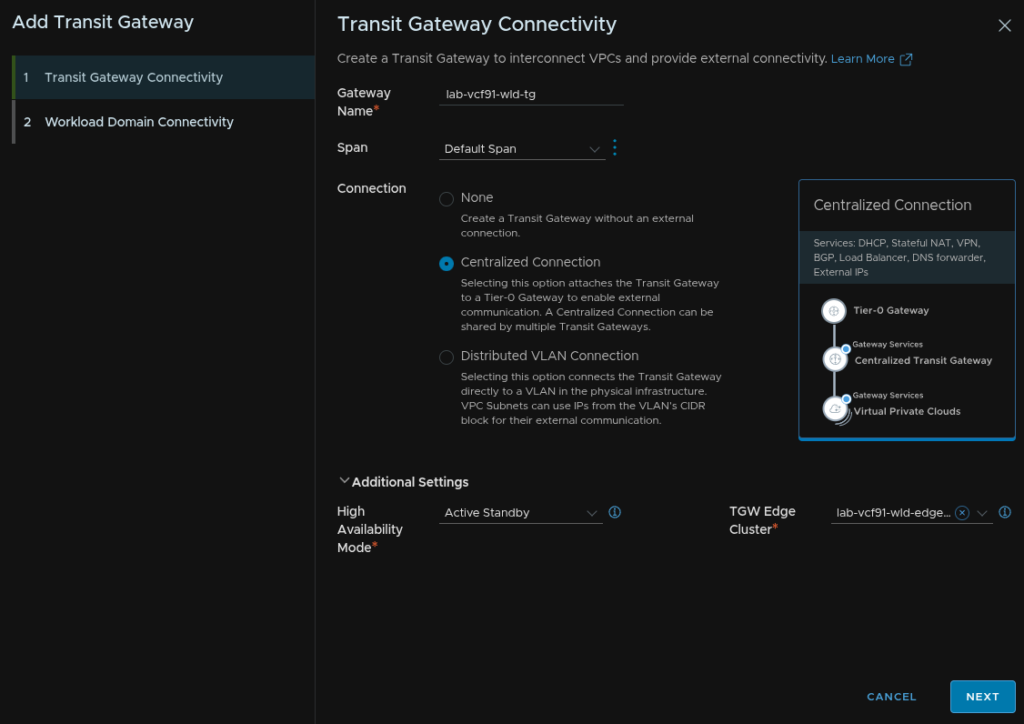
On the vSphere networking tab, right click Virtual private Clouds and click New Transit Gateway
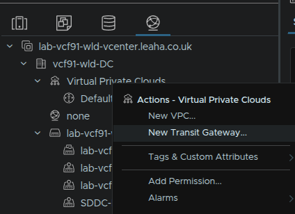
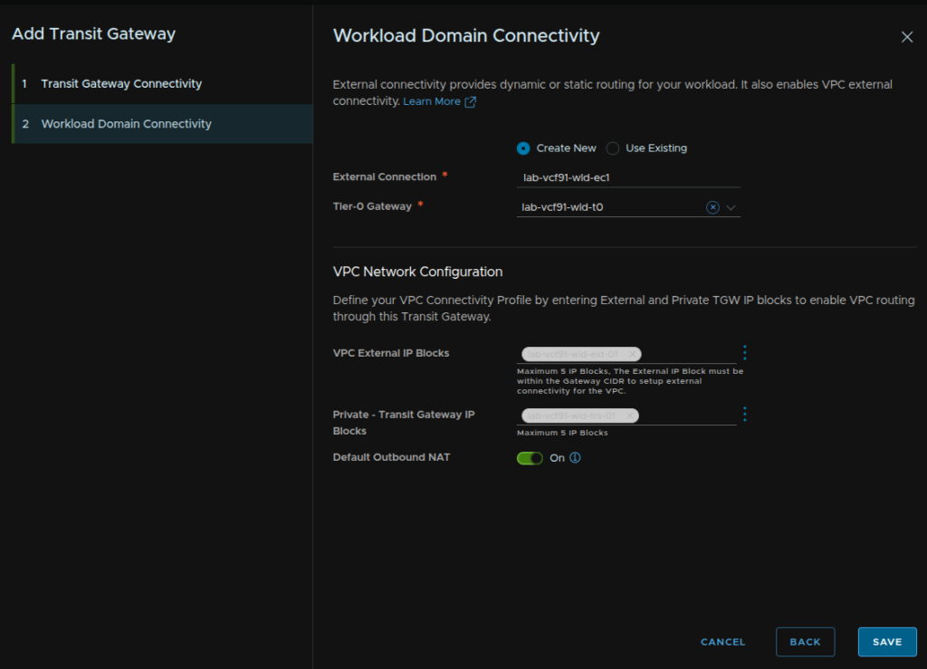
Give the gateway a new name, leave the span on default, select Centralized Connection, for the HA mode, use Active Standby, else the Supervisor and K8S workloads will not work properly with NAT, for the Edge cluster, select our newly deployed cluster, and click Next
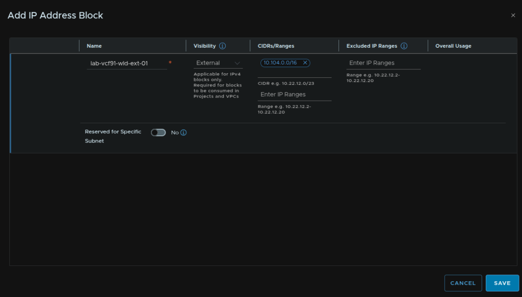
Select the radio button for Create New, then give the external connection a name, then select our new T0 gateway, then for VPC external blocks click the three dots and click Create New
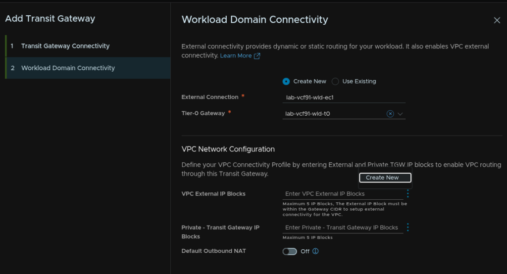
Add a /16 block of IPs to be globally accessible over your datacenter and click Save
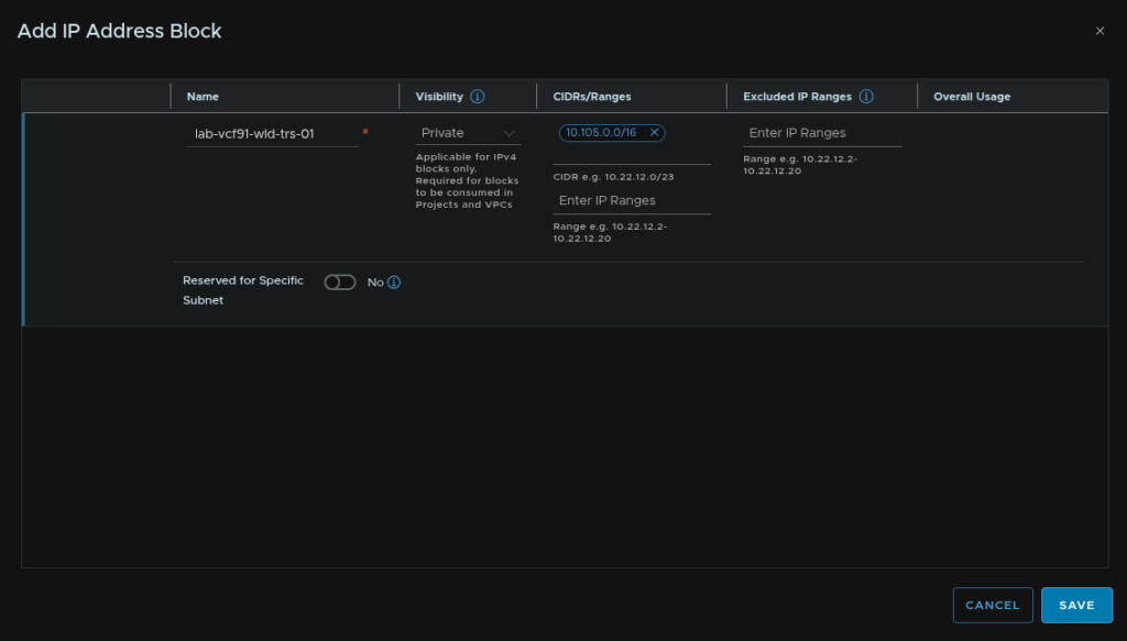
For Private Transit Gateway blocks click the three dots and click Create New
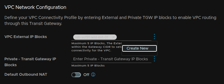
Add another /16 that doesnt overlap anywhere and click Save
Enable Default Outbound NAT and click Save
13.5 – Creating VPCs With Our New Gateway
By default all VPCs land in the default transit gateway and connectivity profile, this is fine for the initial domain, but not so much for our workload domain
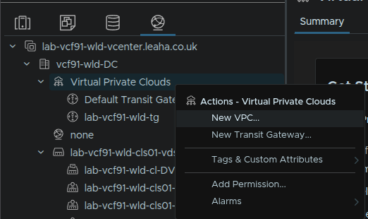
To create a new VPC click the networking tab in vSphere and right click Virtual private Clouds/New VPC
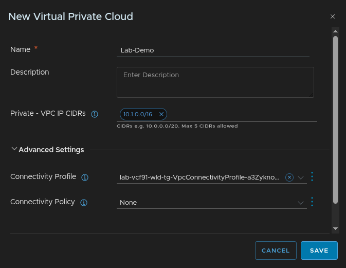
Give the VPC a name, and assign a private IP space, this wants to be another /16 that doesnt overlap anywhere else on the datacenter, this /16 can, be reused over all VPCs, which I typically recommend
Expand Advanced Settings and make sure for the connectivity profile we select the one for our new transit gateway and click Save
Now when we create subnets they will be attached to the correct Edge cluster with the local IP ranges and we dont end up with lots of cross domain routing
We’ll cover more on creating networking in the NSX configuration guide
14 – Expanding A Cluster
While this can be done in vCenter, by default this only works on the management domain, for workload domains, VCF SSO and vCenter linking are required, as this is out of scope for this guide, and not all users will have this, I will be using the SDDC Manager UI, while it is deprecated, when it is fully removed, this correct workflow in vSphere should be sorted
Before we begin here we need to ensure we have a network pool, if you are expanding a cluster you can use the network pool already associated with it, if you are deploying a new cluster you can use the existing network pool or create a new one, so you likely dont need a new one, but you must have one you can use, more info is in section 10.1
Available new hosts must be in the inventory from section 10.2
We also need to have an image imported into the SDDC like in section 11
We need to log into the SDDC Manager UI on
https://fqdn
We will then get redirected to login with the management domain vSphere SSO accounts
Click Inventory/Workload Domains and select the workload domain which is having its cluster expanded, I will be doing this on the vcf9-wld01 domain
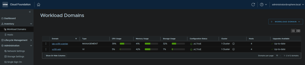
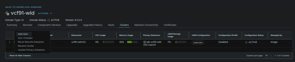
Click the Clusters tab, click the three dots on the cluster and click Add Host
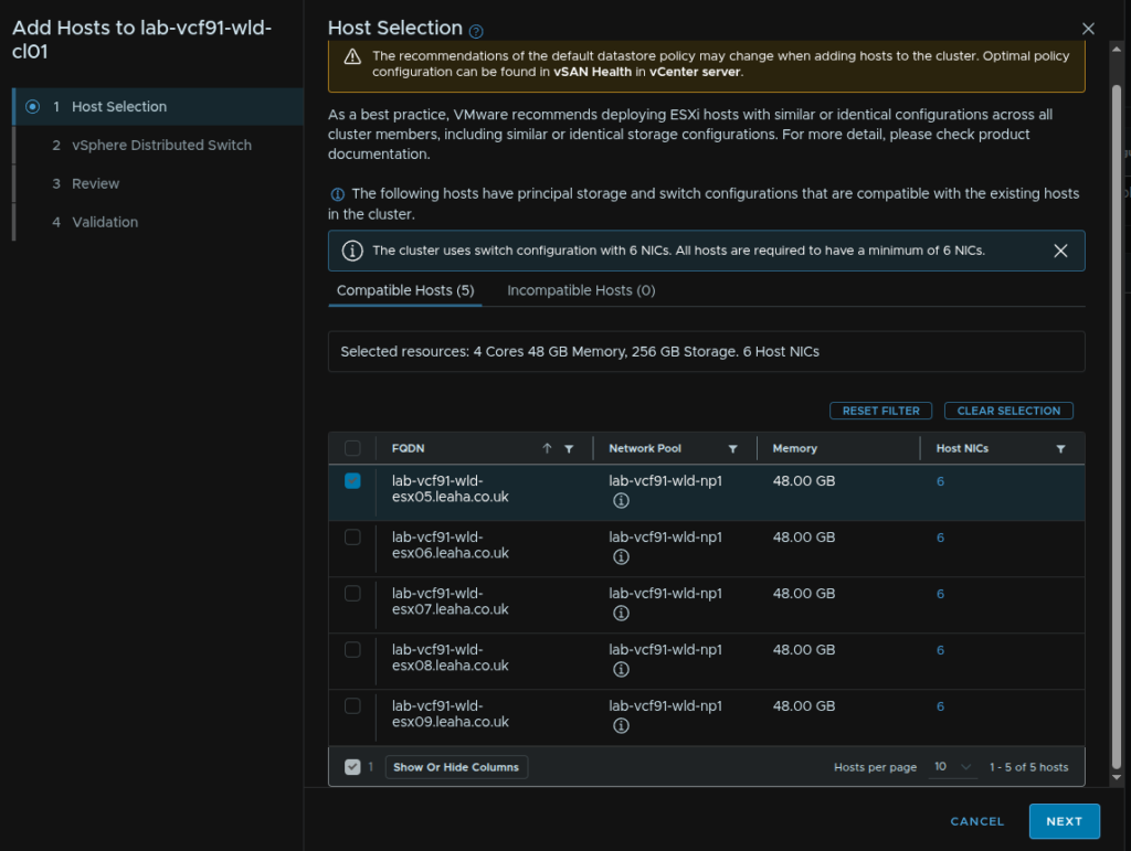
Hosts will need to be compatible with the same principle storage as existing hosts, in my case vSAN, and have the same NIC configuration
Select any hosts to be added and click Next
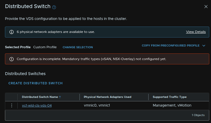
We then need to choose uplinks for the cluster VDS
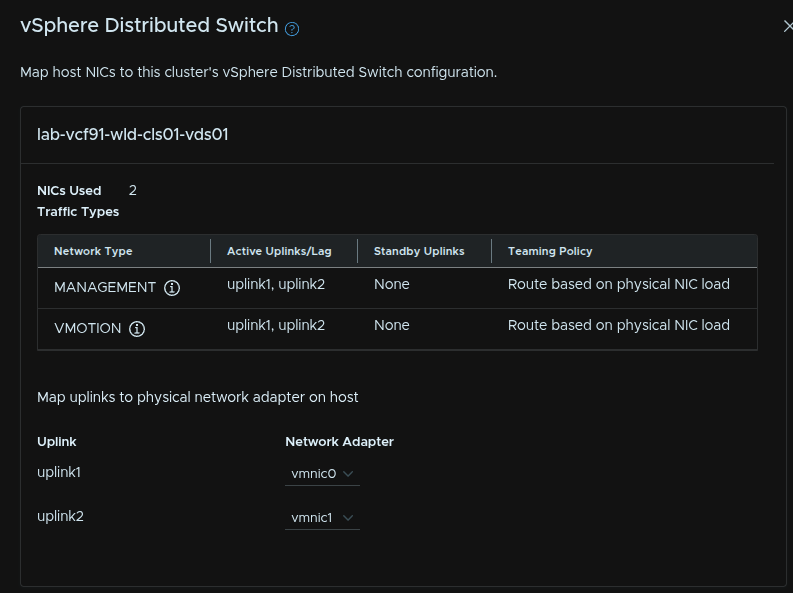
When you are happy, click Next
Click Next
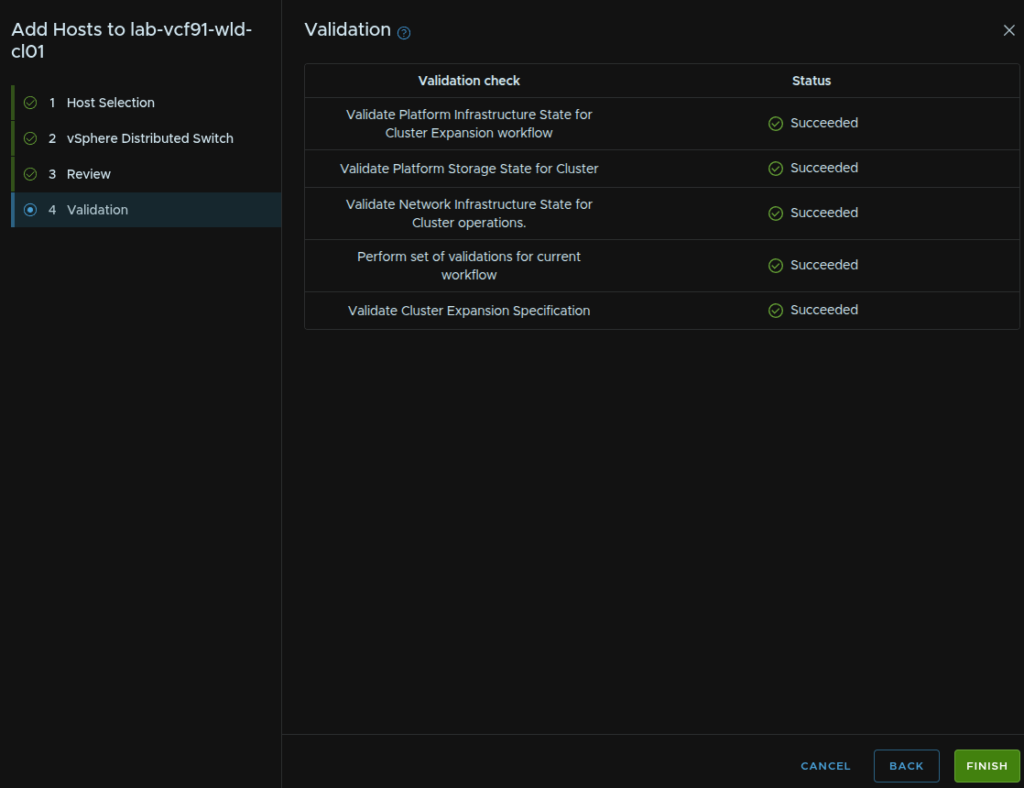
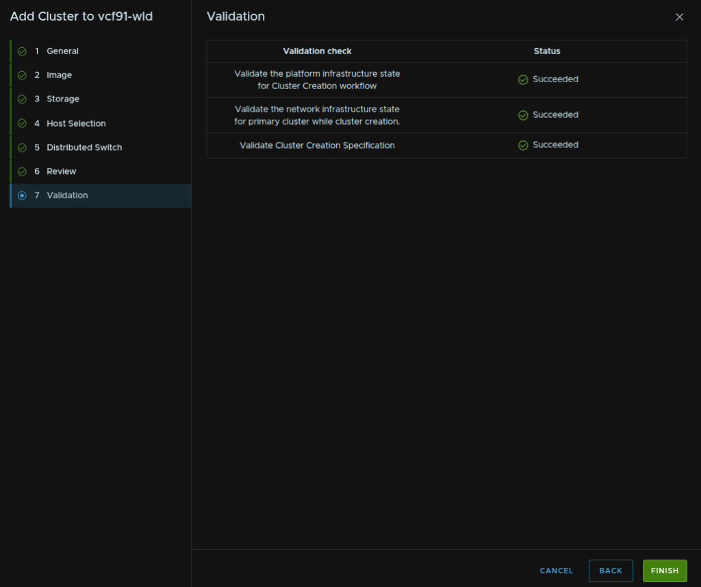
Wait for the validation to succeed and click Finish, if you have errors they will need addressing
15 – Creating A New Cluster
While this can be done in vCenter, by default this only works on the management domain, for workload domains, VCF SSO and vCenter linking are required, as this is out of scope for this guide, and not all users will have this, I will be using the SDDC Manager UI, while it is deprecated, when it is fully removed, this correct workflow in vSphere should be sorted
Before we begin here we need to ensure we have a network pool, if you are expanding a cluster you can use the network pool already associated with it, if you are deploying a new cluster you can use the existing network pool or create a new one, so you likely dont need a new one, but you must have one you can use, more info is in section 10.1
Available new hosts must be in the inventory from section 10.2
We also need to have an image imported into the SDDC like in section 10
15.1 – Starting The Workflow
We need to log into the SDDC Manager UI on
https://fqdn
We will then get redirected to login with the management domain vSphere SSO accounts
Click Inventory/Workload Domains and select the workload domain which is having its cluster expanded, I will be doing this on the vcf9-wld01 domain
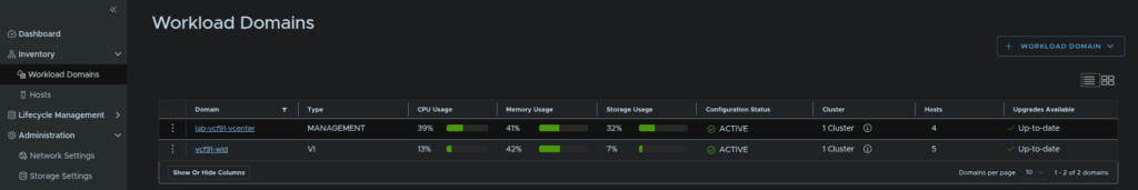
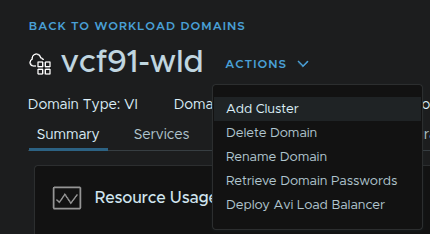
Click Actions/Add Cluster
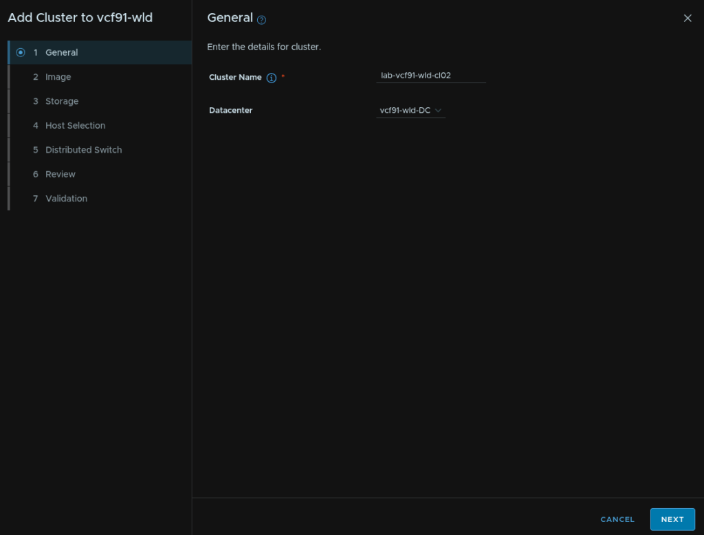
15.2 – General
Enter a cluster name, and select the existing datacenter then click Next
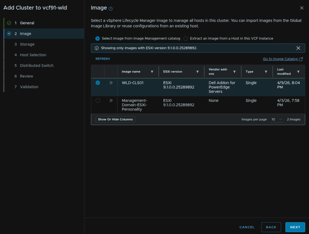
15.3 – Image
Select our image, I will be using the same as my first workload domain cluster, then click Next
15.4 – Storage
Select your storage type
For vSAN select the vSAN type, this will typically be vSAN HCI unless you know you need a vSAN storage/Compute cluster, then click Next
15.5 – Host Selection
Select our hosts and click Next
15.6 – Distributed Switches
We then need to select our networking topology, I recommend 6 NICs using the storage and NSX traffic separation, but if you have only 4 NICs, what I would consider to be the minimum, use storage separation
Now, while we have the defaults, this doesnt actually let you edit the settings, and the issue there is the NSX TEP addresses will be using DHCP when we want an IP pool like the management domain during the deployment, so click Create Custom Switch Configuration at the bottom, and we will manually set up the topology
Click Create Distributed Switch
Add a VDS name and set the MTU, this should be 9000, but in line with what was set for the management domain, for Type, I would use VDS Uplinks, we need 2 uplinks, select the vmnics you want to use then click Configure Network Traffic Type/Management
One of these uplinks should be bound to the vSwitch on the default ESX install
Give the port group a name and select the load balancing policy of route based on physical NIC load then click Save Configuration

Click Configure Network Traffic/vMotion
Give the port group a name and select the load balancing policy of route based on physical NIC load then click Save Configuration
Scroll to the bottom and click Create Distributed Switch
Click Create Distributed Switch
Give the VDS a name, set the MTU the same, which should be 9000, for the Type I recommend VDS Uplink, select the two uplinks you want to bind for storage and click Configure Network Traffic/vSAN
If you chose NFS configure that here
Give the port group a name and set the same load balancing option then click Save Configuration
Then scroll to the bottom and click Create Distributed Switch
Click Create Distributed Switch one last time
Give the VDS a name, set the MTU to the same, at 9000, for the Type I recommend VDS Uplinks, then add the remaining uplinks, then click Configure Network Traffic/NSX
Leave the default boxes checked, all three should be set the transport VLAN for NSX, and for IP Allocation, select Static IP Pool, then click Re-Use An Existing Pool and select the pool used for the first cluster in our workload domain
You can optionally create a new pool with a different VLAN if required
Give the VLAN transport zone a name, the uplink number should match the number on the VDS, in our case, 2, and set the NSX and VDS uplinks to match
Give the NSX uplink profile a name and set the Teaming Policy to Load Balance Source and click Save Configuration
Scroll down and click Create Distributed Switch
Then click Next
Review all the info and when you are happy click Next
Once the validation has passed click Finish
16 – Fleet Scaling
Scaling services in the VCF Services Runtime will cause the cluster to be automatically reconfigured as needed, once there is 7-8 worker nodes, they cluster will replace the default smaller 12vCPU/24GB nodes with 24vCPU/48GB nodes, so scaling components can significantly increase the resource overhead, and they cannot be scaled down
16.1 – VCF Operations
16.1.1 – Scale Up
If you have a small appliance, before scaling out, you’ll want to scale the appliance up to a medium size
We can also scale the disk space this way, independently of the appliance size of you need more storage
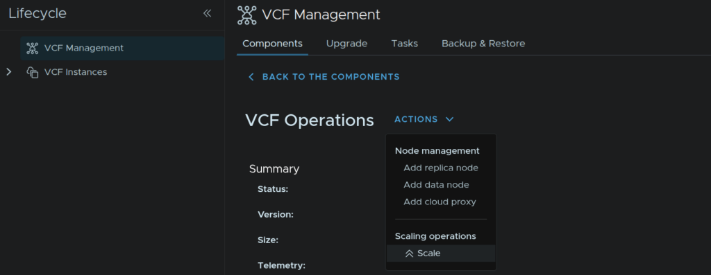
To do this click Build/Lifecycle/VCF Management/Components and click the VCF Operations component
Click Actions/Scale
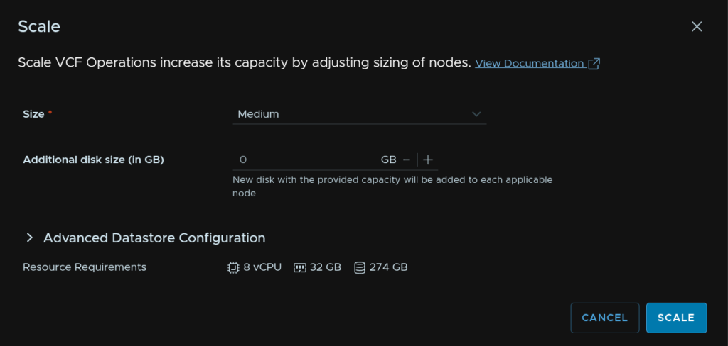
Select the Medium size from the drop down, and optionally you can add additional disk space if the server is filling up, then click Scale
This will shit down the VCF Operations cluster and resize it, then power it back up
16.1.2 – Scale Out
VCF Operations has 3 main node types in a cluster
- Primary node – Cluster leader
- Replica node – Standby copy of the primary node
- Data node – Expands capacity within a cluster and throughput
We will focus on expanding VCF Operations from a single node setup to a three node cluster using high availability, which is the base starting point
Continuous availability can be configured giving you redundancy across VCF Instances/Domains by defining fault domains but its a much more complex process
Beyond this, if you need further capacity with additional data nodes
To do this click Build/Lifecycle/VCF Management/Components and click the VCF Operations component

First lets add a data node, click Actions/Add Data Node
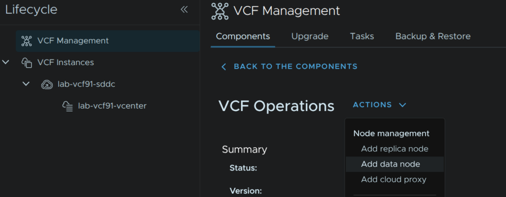
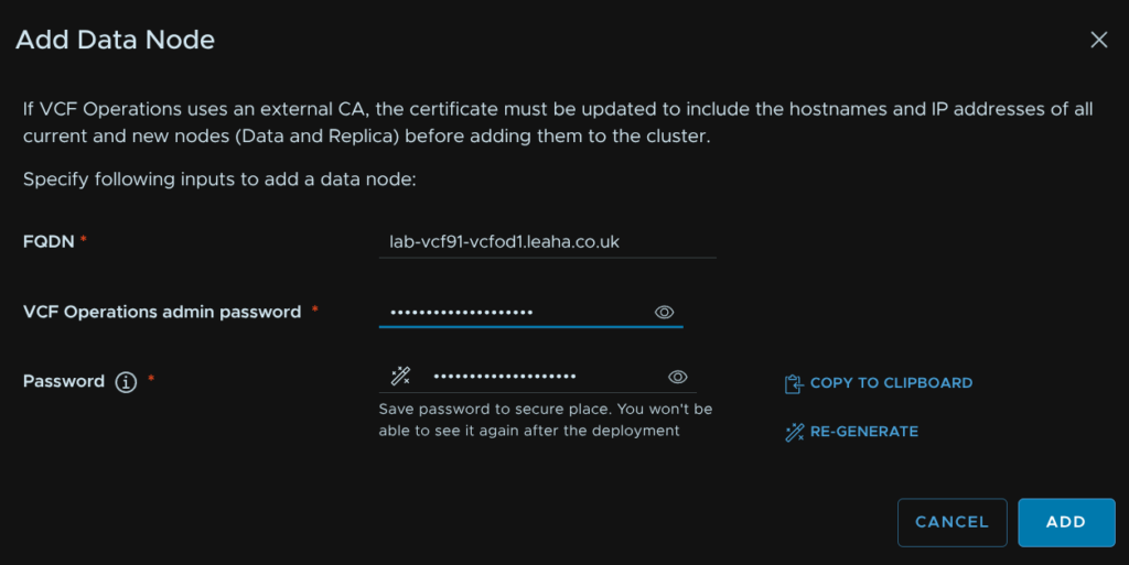
We need an FQDN which must be registered in DNS, then add the VCF Operations admin password, and click Re-Generate for a password for the root user of the Data appliance, you’ll need to note this down and save it, then click Add
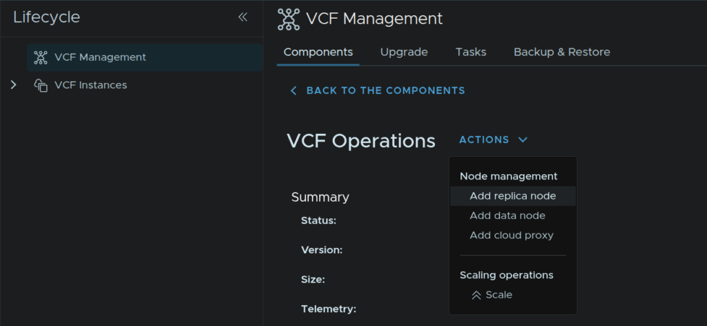
Once thats deployed, check in the tasks and ensure its completed, we can head back to the VCF Operations instance and click Actions/Add Replica Node
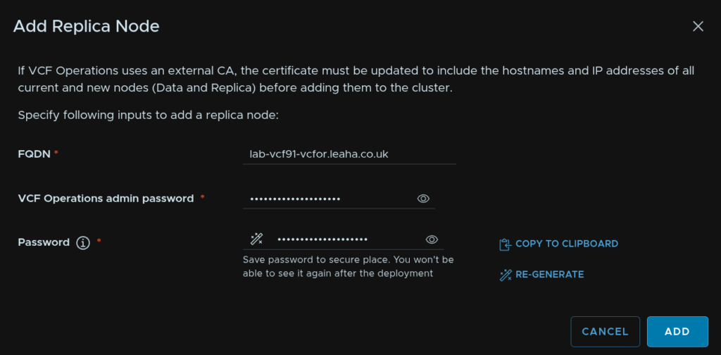
Enter the FQDN, add the Operations admin password, and use the Re-Generate button to generate a root password, you’ll need to save this for later, then click Add
16.2 – VCF Automation
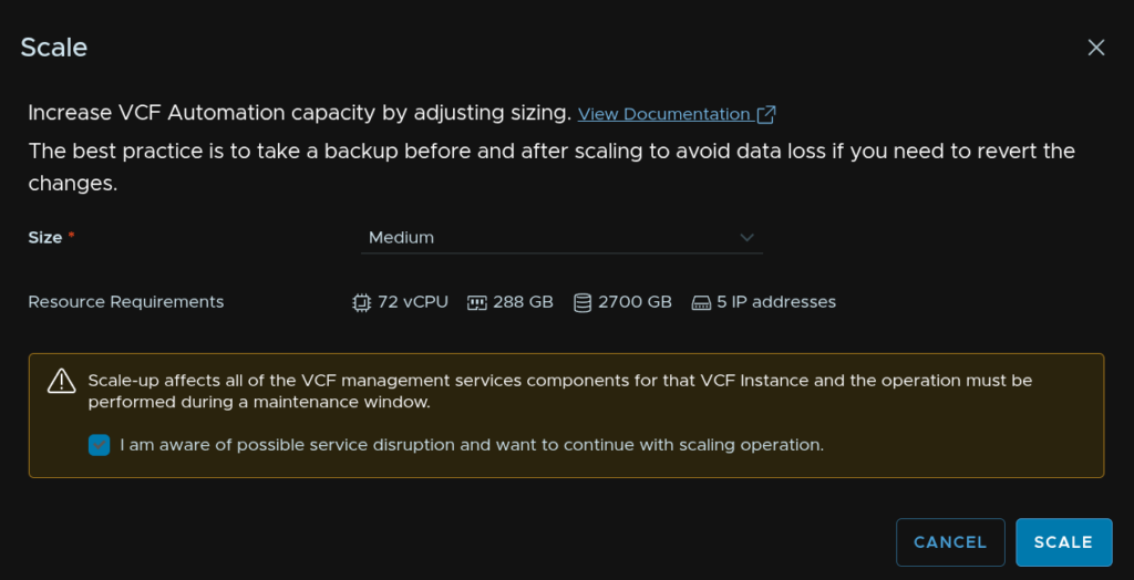
To scale VCF Automation out from a single node deployment to a three node medium cluster, in VCF Operations, click Build/Lifecycle/VCF Management/VCF Automation
Click Actions/Scale
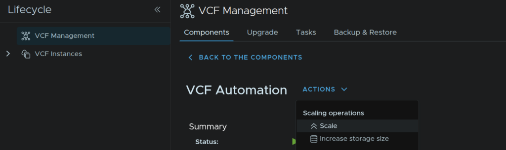
Select the target size, Medium, check the box to acknowledge a potential service outage and click Scale
16.3 – VCF Operations For Networks
16.3.1 – Scale Up
We can increase the brick size of the networks appliance, this is just the overall size, from VCF Operations
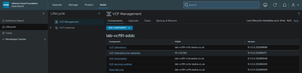
In VCF Operations click Build/Lifecycle/VCF Management/Components then click on the VCF Operations For Networks component

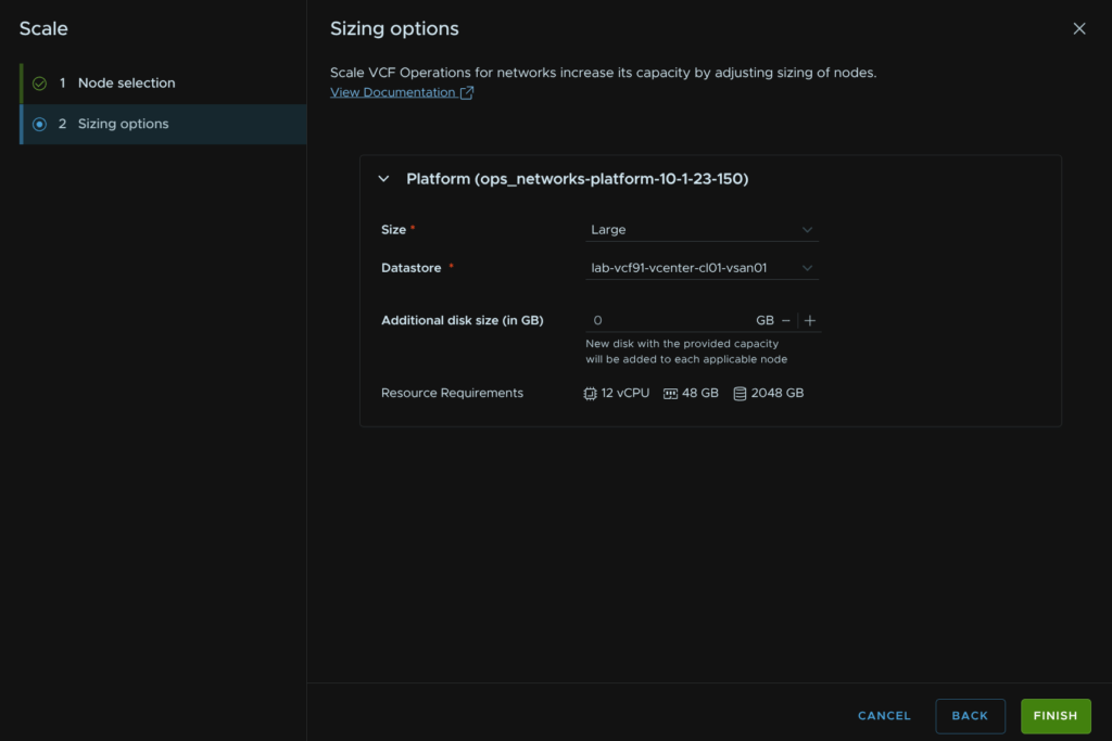
Click Actions/Scale
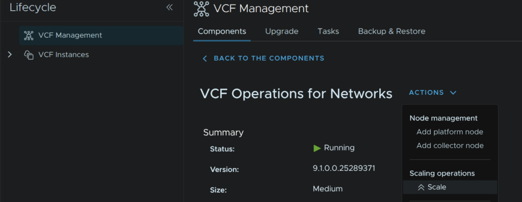
Select the platform node, if you have multiple, all should be configured to be the same size, then click Next
Select the new size and click Finish, you can optionally add additional disk space if needed
16.3.2 – Scale Out
We can scale out VCF Operations For Networks into a HA cluster for the platform nodes, we can also add additional collectors as required
Its worth noting the appliance size should be Large or higher, Medium will fail
For scaling the platform controllers, in VCF Operations click Build/Lifecycle/VCF Management/Components then click on the VCF Operations For Networks component
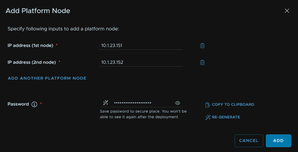
Click Add Platform Node
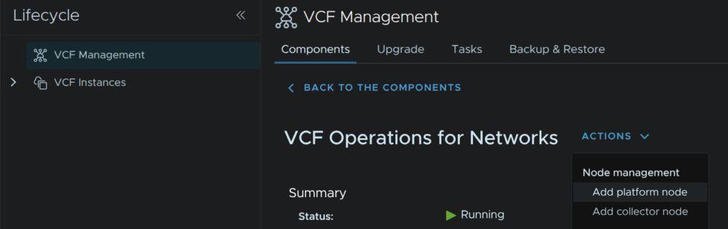
Click Add Another Platform Node so we have two, then enter IP addresses for them, click Re-Generate to create a password and copy it out and save it for later, then click Add
16.4 – Log Management
16.4.1 – Scaling Storage
We can scale storage on the log cluster up to 4TB/replica, which given the small configuration is 8vCPU/16GB, if you need more logs scaling more storage is a good place to start, adding more replicas does allow for further more storage but increases the resource requirement in the VCF Service Runtime
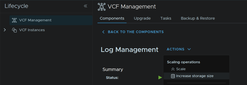
To change this, click Build/Lifecycle/VCF Management/Log Management
Then click Actions/Increase Storage Size
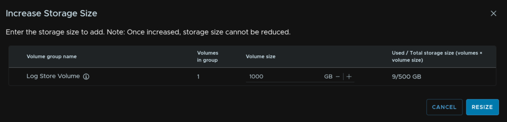
Set the new log store volume amount up to 4000GB, it starts at 500GB, then click Resize
16.4.2 – Scale Out
If we scale out to multiple replicas, this will increase the storage, ~500GB/replica, as well as the compute processing power for the logs cluster
To change this, click Build/Lifecycle/VCF Management/Log Management

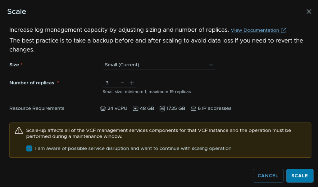
Click Actions/Scale
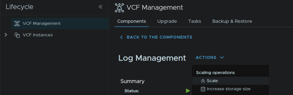
Then add more replicas as needed, the larger node types only offer more CPU/RAM so they might not be needed, when you have the desired number of replicas, Medium/Large require at least three, check the box to acknowledge a potential service outage and click Scale
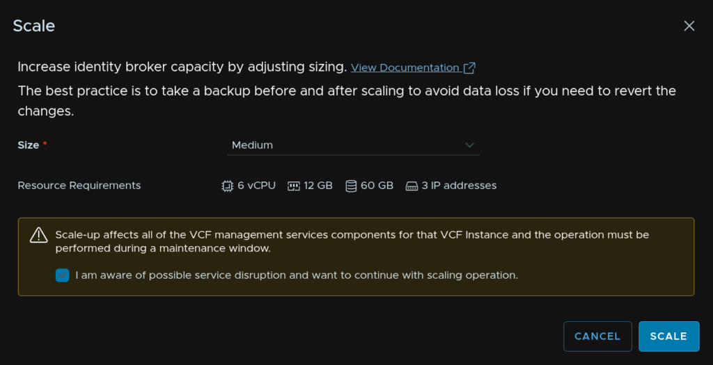
16.5 – Identity Broker
We can scale the Identity Broker out to a three node cluster from VCF Operations
To change this, click Build/Lifecycle/VCF Management/Identity Broker
Click Actions/Scale
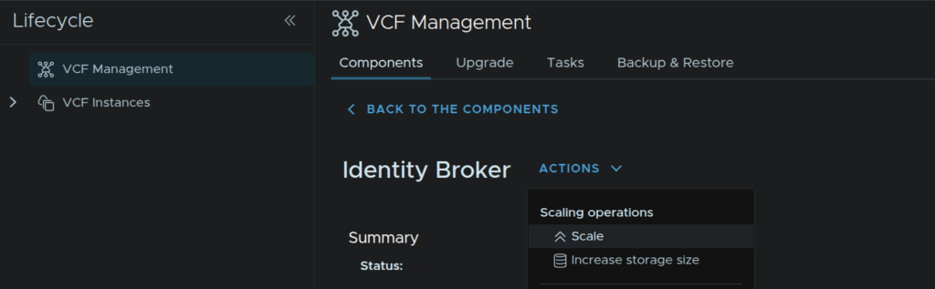
Select the size as Medium, check the box to acknowledge a potential service interruption and click Scale
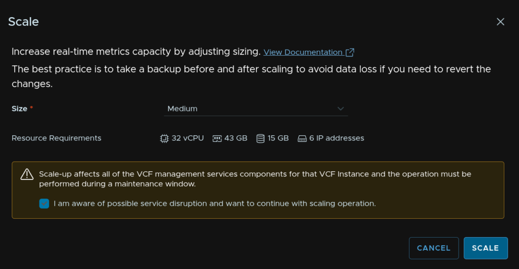
16.6 – Real Time Metrics
16.6.1 – Scale Up
We can scale this up if more compute is needed in larger environments, I would scale this only if you are having performance issues
To scale this, click Build/Lifecycle/VCF Management/Real Time Metrics

Click Actions/Scale
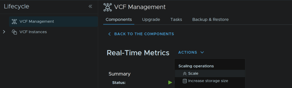
Select the new size, check the box to acknowledge a potential service outage and click Scale
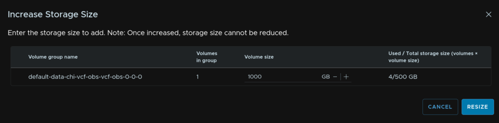
16.6.2 – Add Storage
We can scale storage if more space is needed to store metrics for longer periods of time, this will be needed in larger VCF instances where more hosts are present, the amount thats needed will depend entirely on how fast it fills
You can add more as needed, this cannot be scaled down, so add some storage and keep adding if its not enough
To scale this, click Build/Lifecycle/VCF Management/Real Time Metrics
Click Actions/Increase Storage Size in GB
Enter the amount of storage you want in GB, the default is 500GB, then click Resize
16.7 – Salt
16.7.1 – RaaS
The Salt RaaS service is only hosted in the first VCF Instance, I couldnt find any concrete information on what sizes are needed for what environment size unfortunately, but small will likely be fine for most environments, with medium needed for must larger, multi VCF Instance environments
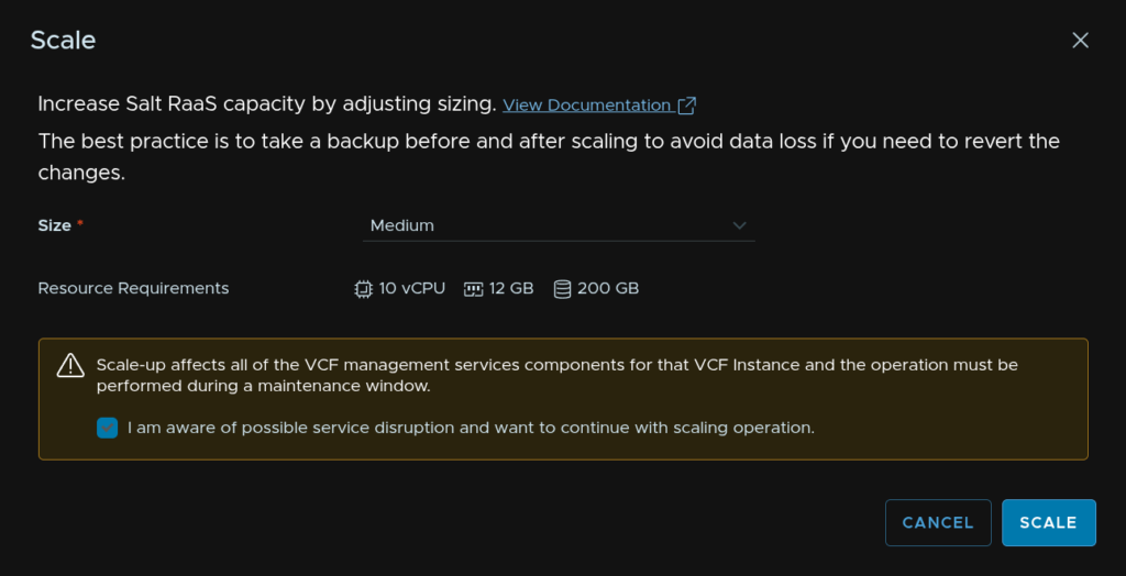
To scale up the Salt RaaS instance, click Build/Lifecycle/VCF Management/Salt RaaS
Click Actions/Scale
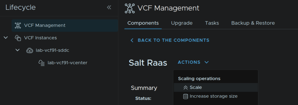
Select the new size, check the box to acknowledge the potential service outage and click Scale
16.7.2 – Master
Salt is a tool for providing configuring and automation at very large scales, so my assumption on the role this now plays in VCF is around the runtime services and what that has to offer
If your VCF instances are going to be large, then scaling the Salt Master and Salt RaaS instances makes sense
I couldnt find any information on sizing from Broadcom, but, per VCF instance, I would take the following as a rough rule of thumb
- Small – Up to ⅓ of the configuration maximum
- Medium – Between 1/3 and ⅔ of The configuration maximum
- Large – Over ⅔ of the configuration maximum
To scale this, lets start with the Salt Master, in VCF Operations, click Build/Lifecycle/VCF Management/Components and click Salt Master
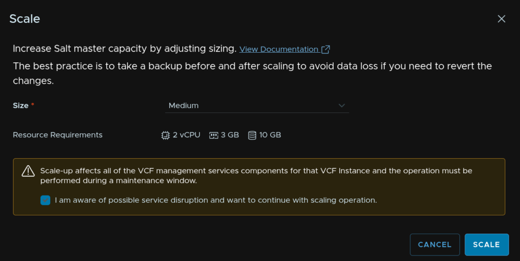
Click Actions/Scale
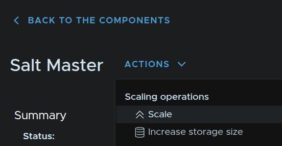
Set the desired size, in my case Medium, check the box acknowledging a potential service outage and click Scale
Wait for this to finish, we can check in on it from the Tasks menu, before scaling the Salt RaaS instance

Hi Leaha,
I see 65 IP addresses used in your deployment.
Is that the minimum IP pool requirements?
Yeah, I went with the minimum that I felt made sense, eg the service runtime I added all 30 IPs, while only 12 was needed for the small deployment, this just meant you would be covered whatever the depployment evolved into down the line
You could absolutely provide the bare minimum and add later if you wanted less IPs upfront
What if you don’t have enough IPs in the management vlan in an upgrade to 9.1. Is there a way to use a different vlan for the 12-30IP requirements?
Not that I know of, you can use the API/JSON deployment you can use a non continuous block, otherwise, I dont know what you can do sadly
If a way exists, its by the API
Thanks. Curious is this requirement (12-30IPs) for a net new deployment. Or is it specific to upgrade to 9.1 (if your already on 9.0 as an example) Thanks
Great writeup Leaha! I am just starting to work on VCF9.1 planning for a rather large estate and this has been most useful.
Im glad you find this helpful 🙂 Always much appreciated
I am getting the last bits finished now the builds are GA for the depot and licensing
Great work Leaha, inpiring as usual!
Great overview, just needed to redeploy my lab because I was too confident my Upgrade from 9.0 would run through without any problems…
Anyone else a bit stumped by the vCPU requirements rising again? I hoped they would optimize the Automation VM a bit, instead we got like 40vCPUs more to run. If this continues the next release will not be able to run in my homelab anymore.
Dont get me started on this… Ive been complaining to Broadcom who are getting a lot of this feedback
They love to slate Nutanix and their CVM requirement, and they market VCF as better, however, in 9.1 this is not true, and VCF is much heavier, they say they are working on it, we will see what happens though
Other good news, I am working on a manual downsize of the cluster to 28vCPU/58GB for homelabs, which is going well and should be published soon ish
Getting it smaller, just isnt feasable sadly
Welp, guess we now know how they argue their pricing policies 😀
Looking forward to that downsize article, and thank you for bringing this to their attention. As one of the few remaining VMware homelabbers, I appreciate it!
Very nice and “clean” article about VCF, Broadcom should be inspired here also 😉 I can’t believe this is still VCF 9.x, but required set of resources are dramatically higher compared to initial release of 9.x. I think that some customers need to buy additional HW prior upgrade to 9.1, especially if “consolidated” domain is in use.
Thank you <3
Yeah.. The resources are a lot, I think most customers will be fine, its not massive for customers running 4+ hosts on 1TB RAM each, potentially, but its still more, and it feels needlessly so, and it can be optimised, which it isnt
9.1 is definitely stretching 'Minor Update'
Definitely, big customers are safe, Broadcom targeting VCF for them. Mid size VCF Management Domain can easily consume 300 cores, mandatory covered by subscription but in comparsion RedHat “Management Cluster” not need to be licensed. So it’s question of time when customer financial report shows in “red”. I’m in contact with Broadcom people, they are promising some sort of optimization. I’m fan of VMware products (also desktop part, now OmniSSA), but still more often customers challenging me how to pay less for same set of services/features. This is not technical issue, this is real demand. It also drives me crazy permanent changes in price list, discounts, blackouts, etc, it takes me 2-3x more time to prepare valid offer for licenses.
You have used different IP addresses for VCF Automation, Automation Service Runtime, and the VCF Management Component (Service Runtime). These IP addresses are not part of the IP pool that was assigned to them. Is it necessary to assign separate IP addresses to these components outside of the defined IP pool?
lab-vcf91-vcfa.leaha.co.uk 10.1.23.140 VCF Automation
lab-vcf91-vcfasr.leaha.co.uk 10.1.23.174 VCF Automation Service Runtime
lab-vcf91.vcfols.leaha.co.uk 10.1.23.170 VCF License Server
lab-vcf91-vcfis.leaha.co.uk 10.1.23.171 VCF Instance Services FQDN
lab-vcf91-vcfib.leaha.co.uk 10.1.23.172 Identity Broker
lab-vcf91-vcfsr.leaha.co.uk 10.1.23.173 VCF Service Runtime FQDN
Yes, the service IP pool used in the VCFA anf VCF Management service runtimes are used for the K8S nodes and are separate from the FQDNs to access the services
The table is correct for IP and FQDN requirements