Last updated on May 6th, 2026 at 18:50
In this guide we will be taking a look through the deployment of the full VCF 9 suite, using the new easy installer
We will go through installing and configuring ESX for the management network and setting the certificates up, I will give a very rough overview of the networking, but this varies per vendor and wont be covered in great detail
Then, deploying the VCF installer appliance, which will build the foundation of the environment where we can continue with some day 2 deployment steps
So what is included with VCF 9
- SDDC Manager
- vCenter
- vSAN (1TiB/Core)
- NSX
- Supervisor/VKS/Tanzu
- VCF Operations (Aria)
- VCF Automation (Aria)
- VCF Operations For Logs (Aria)
- VCF Operations For Networks (Aria)
- Private AI Service
The deployment of the private AI service isnt in this deployment guide as I dont have the GPUs/Nvidia vGPU licenses for it
We will want a minimum of two nodes running Fibre Channel or NFS storage, or three for vSAN. though I recommend four as a minimum for vSAN, in this guide we will be looking at vSAN for storage
iSCSI storage is supported but not a principle storage, only as supplemental so you will need one of the above types for some of the appliances
Here is a bill of materials for everything we will be deploying for our management domain
- vCenter – 4vCPU 21GB
- 3x NSX Manager – 6vCPU 24GB
- 1x SDDC Manager – 4vCPU 16GB
- vSAN ~32GB in RAM Cache
- 2x Edge Nodes – 8vCPU 32GB
- 3x Control Plane Supervisor Nodes – 4vCPU 16GB
- Fleet Management – 4vCPU 12GB
- VCF Operations – 4vCPU 16GB
- VCF Operations Collector – 4vCPU 16GB
- VCF Automation – 24vCPU 96GB
- VCF Operations For Logs – 8vCPU 16GB
- VCF Operations For Networks Controller – 8vCPU 32GB
- VCF Operations For Networks Collector – 4vCPU 12GB
You will want a minimum of four NICs per host, I recommend six which is what I am using, we will also want to consider the following
Physical Network
Here, they key takeaway, is all switch ports need to be the same, with an MTU of 9216, not in a LAG or port channel of any kind of logical NIC grouping, VLT/VSX/MC-LAG will still work
And example of the port configured on my switch, has the native VLAN on the default 1, though it is best practices to change this, eg 4092, I have the needed VLANs trunked, this included other VLANs VMs may need, and an MTU of 9216, here is what I have on my Dell OS10 switch
interface ethernet1/1/44
no shutdown
switchport mode trunk
switchport access vlan 1
switchport trunk allowed vlan 1023-1040
mtu 9216
flowcontrol receive on
- Top of Rack switches are configured. Each host and NIC in the management domain must have the same network configuration. No ethernet link aggregation technology (LAG/VPC/LACP) is being used
- IP ranges, subnet mask, and a reliable L3 (default) gateway for each VLAN are provided
- Jumbo Frames (MTU 9000) are recommended on all VLANs. At a minimum, MTU of 1600 is required on the NSX Host Overlay VLAN and must be enabled end to end through your environment
- VLANs for management, vMotion, vSAN/NFS and NSX Host Overlay networks are created and tagged to all host ports. Each VLAN is 802.1q tagged
- Management IP is VLAN backed and configured on the host. vMotion & vSAN IP ranges are configured during the deployment process
Physical Hardware And ESX Hosts
- All servers are vSAN compliant and certified on the VMware Hardware Compatibility Guide, including but not limited to BIOS, HBA, SSD, HDD, etc
- Identical hardware (CPU, Memory, NICs, SSD/HDD, etc.) within the management cluster is highly recommended. Refer to vSAN documentation for minimal configuration
- Hardware and firmware (including HBA and BIOS) is configured for vSAN
- One physical NIC is configured and connected to the vSphere Standard switch. The second physical NIC is not configured
- Physical hardware health status is ‘healthy’ without any errors
- ESXi is freshly installed on each host. The ESXi version matches the build listed in the Cloud Foundation Bill of Materials
- All hosts are configured and in synchronization with a central time server (NTP). NTP service policy set to ‘Start and stop with host’
- Each ESXi host is running a non-expired license – initial evaluation license is accepted
Supporting Infrastructure
- All hosts are configured with a DNS server for name resolution. Management IP of hosts is registered and queryable as both a forward (hostname-to-IP), and reverse (IP-to-Hostname) entry
- Either the primary or secondary DNS servers should be hosted outside the VCF private cloud
For the different networks we will need a minimum of seven VLANs, I added my VLANs which are used over the guide, additional are required for workload domains
Management Domain
- Management – VLAN 1023
- vMotion – VLAN 1024
- vSAN – VLAN 1025
- NSX Host TEP – VLAN 1027
- NSX Edge TEP – VLAN 1028
- Edge Uplink 1 – VLAN 1029
- Edge Uplink 2 – VLAN 1030
Workload Domain
- ESX Management – VLAN 1031
- vMotion – VLAN1032
- vSAN – VLAN 1033
- NSX Host TEP – VLAN 1034
- NSX Edge TEP – VLAN 1035
- Edge Uplink 1 – VLAN 1036
- Edge Uplink 2 – VLAN 1037
Before we start we will need to get our DNS systems pre registered to avoid any conflicts during the VCF Installer, here is a full list of all my IP addresses for the management domain during the initial deployment and workload domain
Management Domain FQDN Table
| FQDN | IP Address | Purpose |
| lab-vcf9-sddc.leaha.co.uk | 10.1.23.9 | SSDC Manager |
| lab-vcf9-mgmt-vcenter.leaha.co.uk | 10.1.23.10 | vCenter |
| lab-vcf9-mgmt-esx01.leaha.co.uk | 10.1.23.11 | ESX Host 1 |
| lab-vcf9-mgmt-esx02.leaha.co.uk | 10.1.23.12 | ESX Host 2 |
| lab-vcf9-mgmt-esx03.leaha.co.uk | 10.1.23.13 | ESX Host 3 |
| lab-vcf9-mgmt-esx04.leaha.co.uk | 10.1.23.14 | ESX Host 4 |
| lab-vcf9-vcfo.leaha.co.uk | 10.1.23.21 | VCF Operations |
| lab-vcf9-vcffm.leaha.co.uk | 10.1.23.22 | Fleet Management |
| lab-vcf9-mgmt-vcfoc.leaha.co.uk | 10.1.23.23 | VCF Operations Collector |
| lab-vcf9-vcfa.leaha.co.uk | 10.1.23.24 | VCF Automation |
| 10.1.23.25-26 | VCF Automation Node IPs | |
| lab-vcf9-mgmt-nsx.leaha.co.uk | 10.1.23.27 | NSX VIP |
| lab-vcf9-mgmt-nsx01.leaha.co.uk | 10.1.23.28 | NSX Node 1 |
| lab-vcf9-mgmt-nsx02.leaha.co.uk | 10.1.23.29 | NSX Node 2 |
| lab-vcf9-mgmt-nsx03.leaha.co.uk | 10.1.23.30 | NSX Node 3 |
| lab-vcf9-vcfol.leaha.co.uk | 10.1.23.31 | VCF Operations For Logs |
| lab-vcf9-vcfon.leaha.co.uk | 10.1.23.32 | VCF Operations For Networks Platform |
| lab-vcf9-vcfonc.leaha.co.uk | 10.1.23.33 | VCF Operations For Networks Collector |
| lab-vcf9-edge01.leaha.co.uk | 10.1.23.35 | NSX Edge 1 |
| lab-vcf9-edge02.leaha.co.uk | 10.1.23.36 | NSX Edge 2 |
| 10.1.23.50-54 | Supervisor Control Plane Management |
Workload Domain FQDN Table
| FQDN | IP Address | Purpose |
| lab-vcf-wld-vcenter.leaha.co.uk | 10.1.23.64 | vCenter |
| lab-vcf-wld-esx01.leaha.co.uk | 10.1.31.11 | ESX Host 1 |
| lab-vcf-wld-esx02.leaha.co.uk | 10.1.31.12 | ESX Host 2 |
| lab-vcf-wld-esx03.leaha.co.uk | 10.1.31.13 | ESX Host 3 |
| lab-vcf-wld-esx04.leaha.co.uk | 10.1.31.14 | ESX Host 4 |
| lab-vcf-wld-esx05.leaha.co.uk | 10.1.31.15 | ESX Host 5 |
| lab-vcf-wld-esx06.leaha.co.uk | 10.1.31.16 | ESX Host 6 |
| lab-vcf-wld-esx07.leaha.co.uk | 10.1.31.17 | ESX Host 7 |
| lab-vcf-wld-esx08.leaha.co.uk | 10.1.31.18 | ESX Host 8 |
| lab-vcf-wld-esx09.leaha.co.uk | 10.1.31.19 | ESX Host 9 |
| lab-vcf-wld-vcfoc.leaha.co.uk | 10.1.23.65 | VCF Operations Collector |
| lab-vcf-wld-nsx.leaha.co.uk | 10.1.23.60 | NSX VIP |
| lab-vcf9-mgmt-nsx01.leaha.co.uk | 10.1.23.61 | NSX Node 1 |
| lab-vcf9-mgmt-nsx02.leaha.co.uk | 10.1.23.62 | NSX Node 2 |
| lab-vcf9-mgmt-nsx03.leaha.co.uk | 10.1.23.63 | NSX Node 3 |
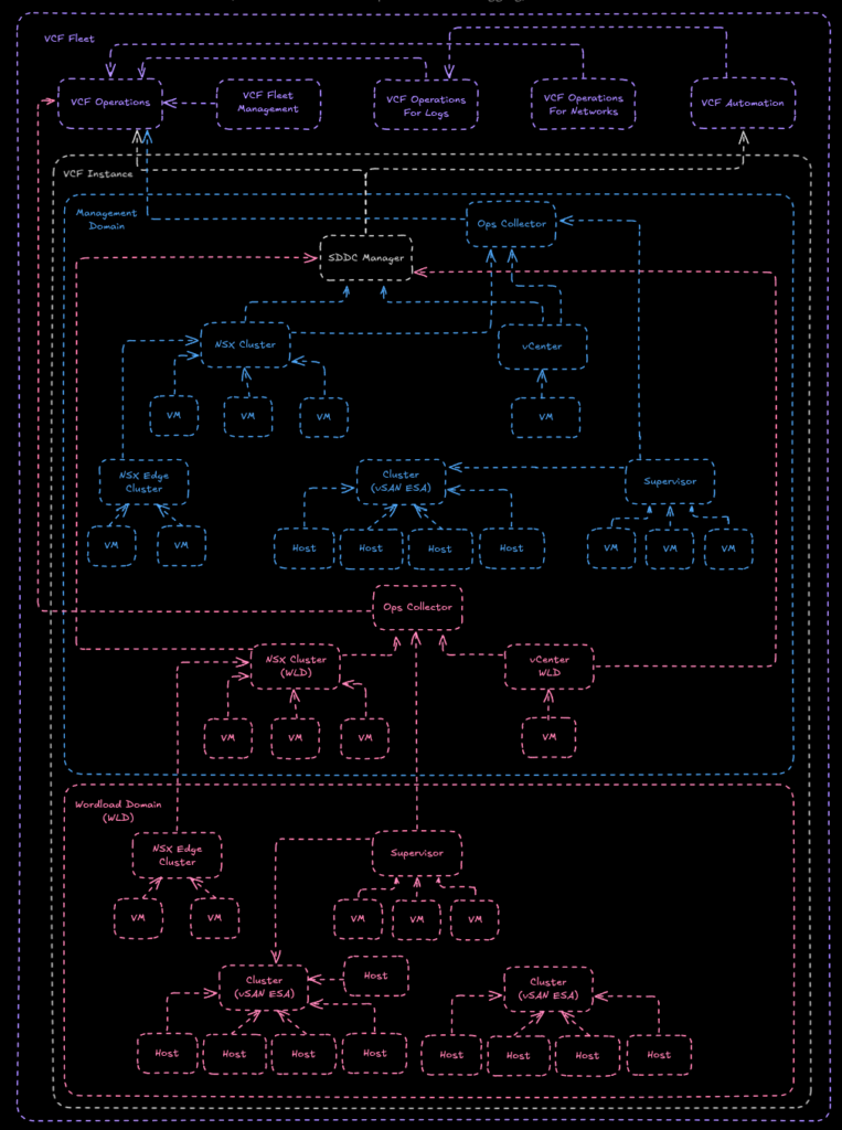
I also find that understanding how things flow and are set out in a diagram helps, this is a topology diagram of what we will be deploying, bare in mind VCF 9 topology is not set in stone, for example, the first domain is called the management domain, but you can use it for management and workloads if you want
Important – By continuing you are agreeing to the disclaimer here
1 – ESX
1.1 – Installation
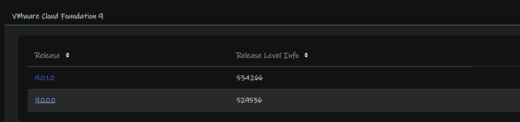
In order to install ESXi you’ll need the ESXi ISO from Broadcom, you can find this under VMware Cloud Foundation
Expanding VMware Cloud Foundation 9 and select the release you want to deploy, I am deploying 9.0.0.0 so I clicked that release

Click View Group on VMware ESX

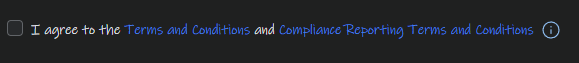
Accept the T&Cs, you need to click the links, then the box can be checked
And Download the ISO Image

Mount this to the server, by using rufus to create a bootable USB, or by mounting it to your servers virtual CD ROM in the IPMI, iDRAC for Dell and iLO for HPE
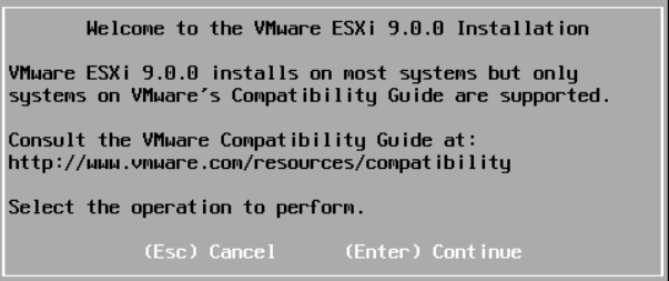
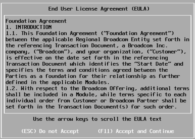
Once the server has booted ESXi, you’ll have this screen, select enter to continue
Accept the EULA with F11
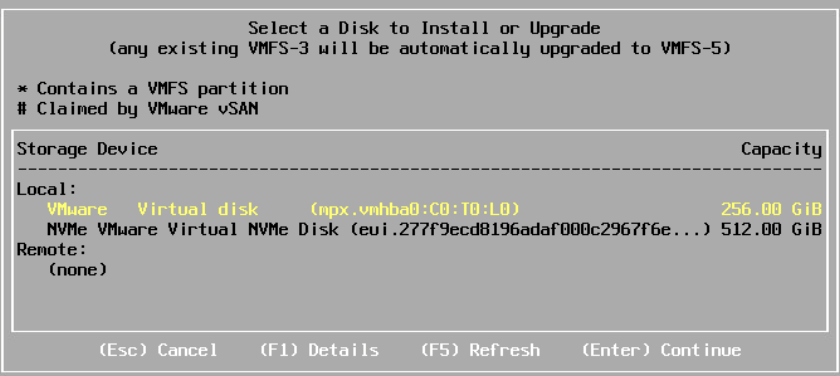
It will then scan for bootable devices, for a production system this should be something in RAID 1
Examples are Dell’s BOSS card
For HPE G11 you should have the NS204i-U, or for G10 systems the NS204i-P, which is a PCIe card
As this is a lab, I have a virtual disk, and will be using the 128GB one by making sure its highlighted in Yellow and clicking Enter to Continue
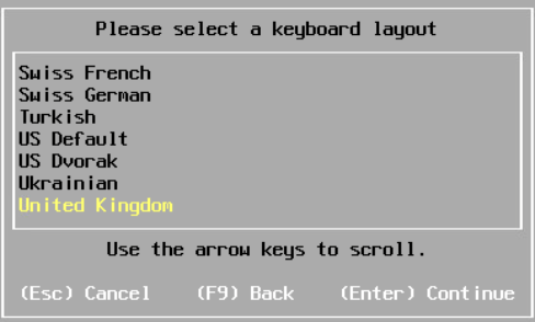
Select your keyboard layout and hit Enter
Set a root password, use something easy to use, we can set a secure random one later
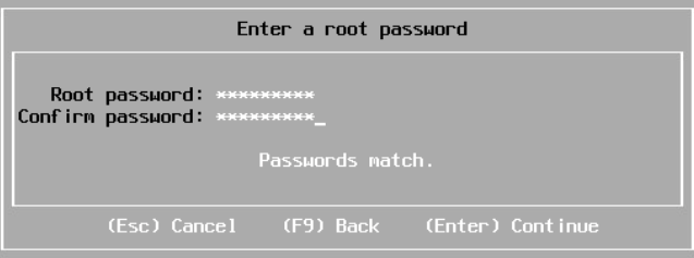
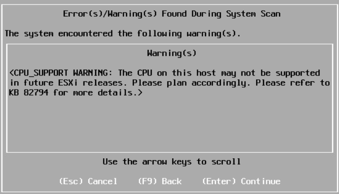
You may get a CPU warning depending on your hardware, I have a 3rd Gen Epyc CPU which flagged this, it is supported but may not be in a future release
Press Enter
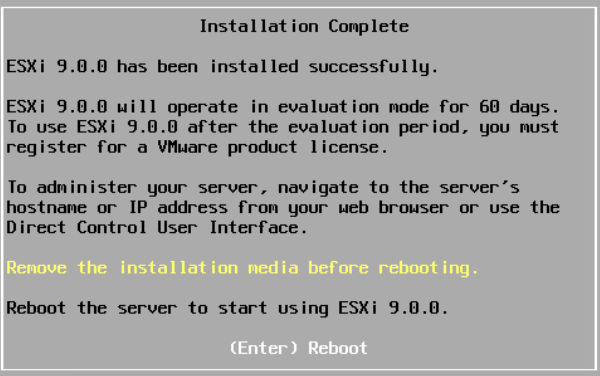
Then click F11 to install
Once thats done, reboot the server when prompted and unmount your media
1.2 – Configuring ESX
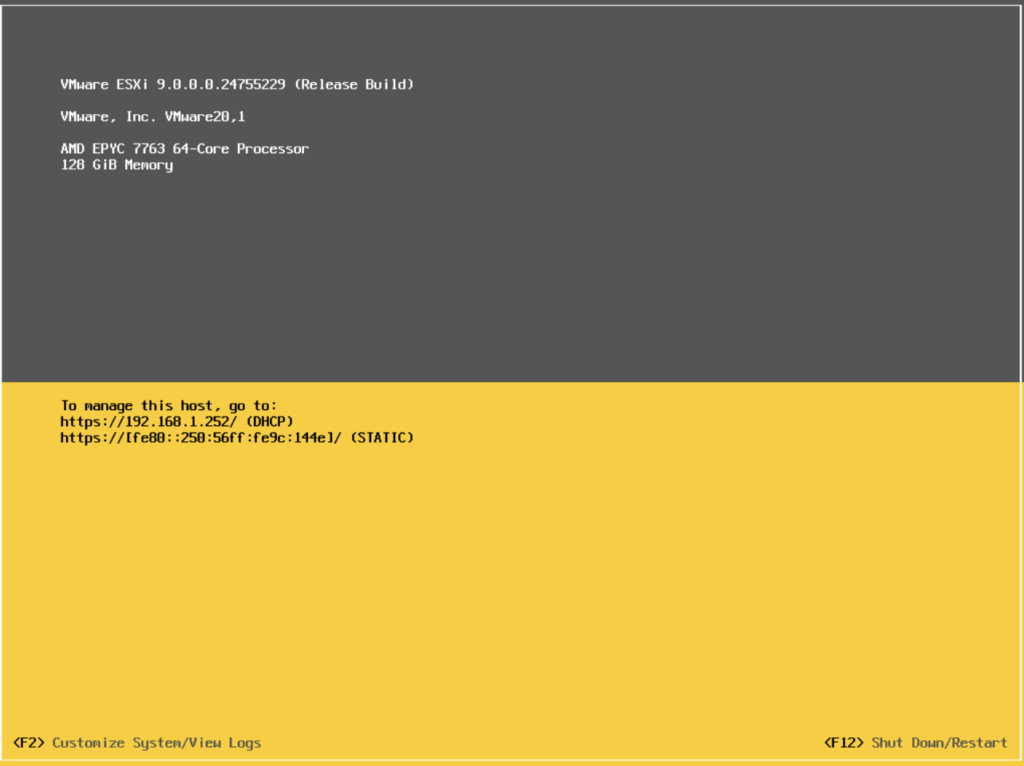
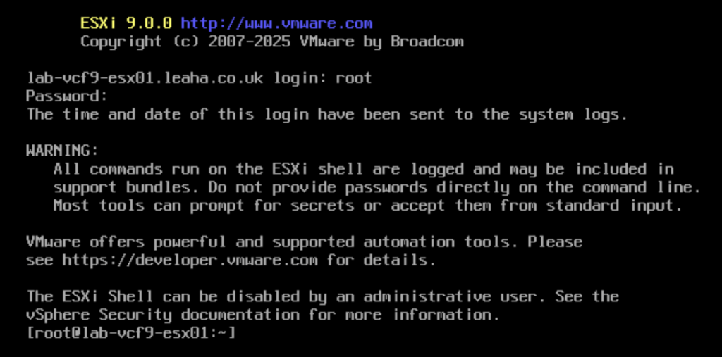
When the host boots, it should look like this, press F2 to login
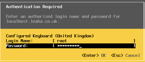
Enter the root credentials and press enter
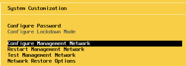
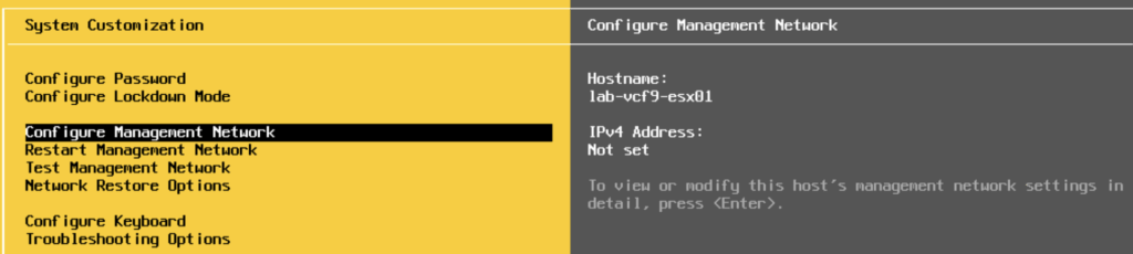
Scroll to Configure Management Network and press enter
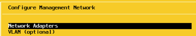
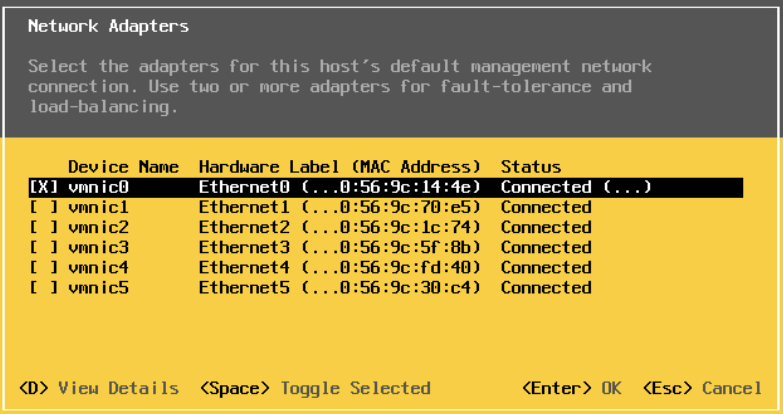
Press Enter on Network Adapters and ensure that a connected Nic is selected, these should all be configured the same on the switch
In my case VMNIC0 is connected, and I will be using this for management, so I will press Escape and leave it as it is
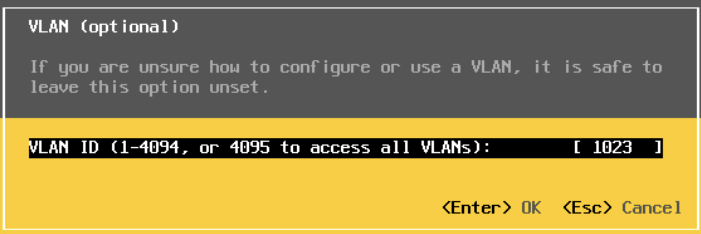
Press enter on VLAN
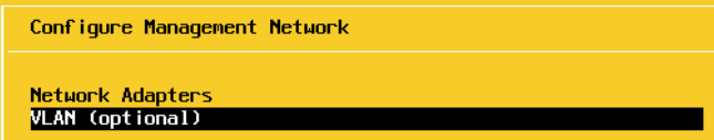
And enter your ESXi management VLAN, I am using VLAN 1023
This is only needed if you have your VLANs trunked down, if your management VLAN is the native VLAN you can ignore this, as all my VLANs are trunked down, I am entering mine
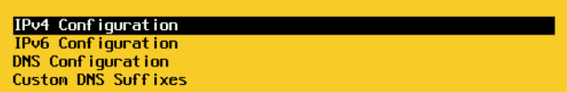
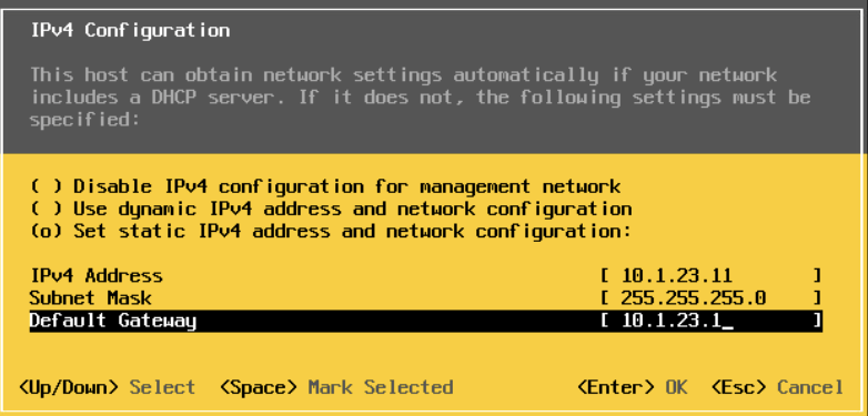
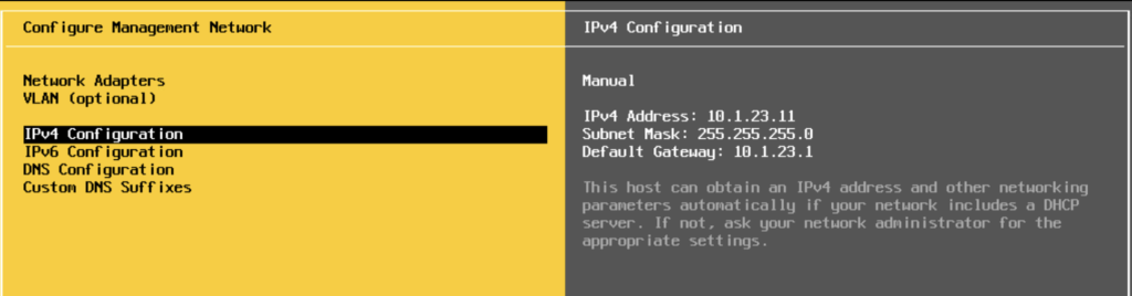
On IPv4
Use the space bar to select the third option to set a static IP and add your management IP details in and press enter to Save
For IPv6, select disable on the first option, unless you are specifically using it, and press Enter

Add your DNS servers and the hostname for this server and press Enter
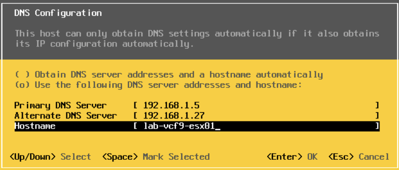
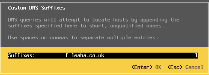
Add your domain under DNS Suffixes and press Enter
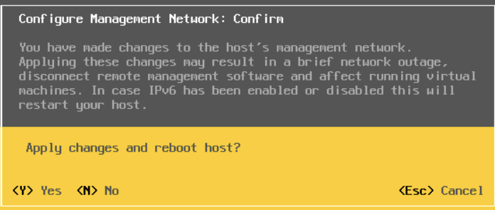
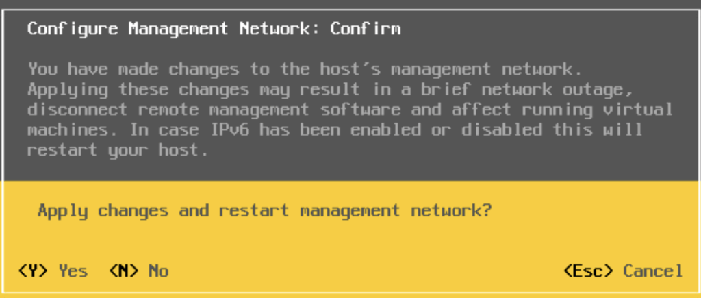
Now press Escape and enter Y to apply changes and reboot the host
Then, login on the WebUI at
https://fqdn
And login with the root credentials
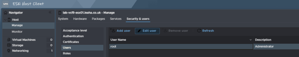
Navigate to Manage/Security & Users/Users on the left, and click the root account and click Edit User to change the root password to something more secure
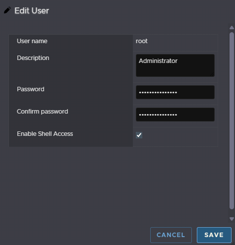
Then add the password
This needs to be 15 characters with the only allowed special characters being !@#$%^&*
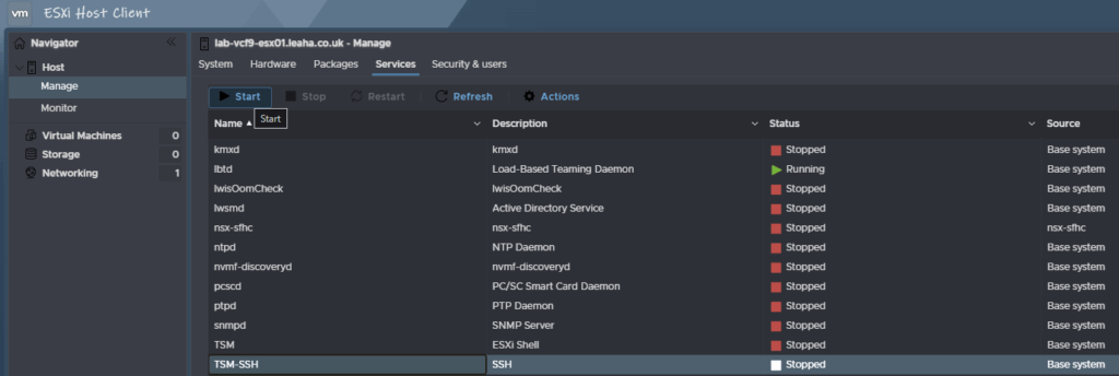
Then we need to enable SSH, click Manage/Services then click TSM-SSH and click Start
Now we need to SSH into the host with the root credentials, using something like Putty and run the following to set the hostname/FQDN correctly for the certificate and renew it for the VCF deployment wizard
For my host, lab-vcf9-esx01, lets set the hostname with
esxcli system hostname set -H=<hostname>So for my host this is
esxcli system hostname set -H=lab-vcf9-esx01Then set the FQDN with
esxcli system hostname set -f=<fqdn>Which for my host is
esxcli system hostname set -f=lab-vcf9-esx01.leaha.co.ukNow renew the certificates with
/sbin/generate-certificatesAnd reboot the host with
rebootWhen it comes back up, you will need to restart SSH for the Installer
Lastly, we need to setup NTP on all servers, you can use a windows App, DC or a docker container, for this
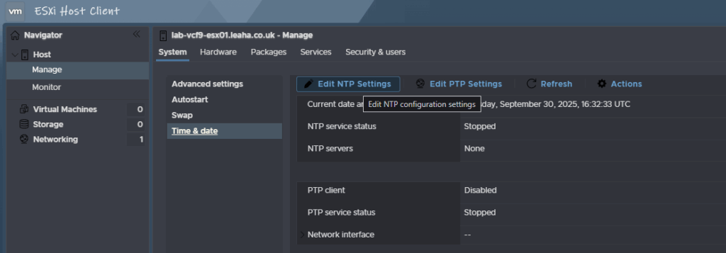
Head to Manager/System/Time & Date, and click Edit NTP Settings
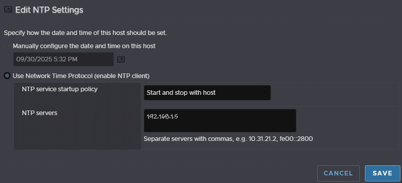
Select the second radio button to use a NTP server, select the service to start and stop with the host, and put the IP address for your NTP server and click save
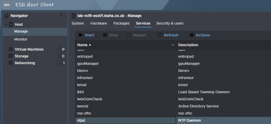
Then, under services, click ntpd, and click start
We will need to repeat this on the remaining hosts
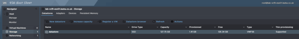
Before we proceed we need to check we have enough space on the first host to deploy the VCF installer appliance, your boot device will typically be 512GB or larger so there should be a good size local datastore created we can use for this as we cant use our vSAN disks
We can check this under Storage/Datastores
Mine is only 128GB but should be enough
If you are doing this as a nested lab for learning purposed, I would suggest doing section 2.14.2 here, before going through the installer
2 – VCF Installer
2.1 – Deploying The Appliance
We first need the appliance OVF, this can find this under VMware Cloud Foundation

Expanding VMware Cloud Foundation 9 and select the release you want to deploy, I am deploying 9.0.0.0 so I clicked that release
Click View Group on the VMware Cloud Foundation Installer

Accept the T&Cs, you need to click the links, then the box can be checked

And download the appliance

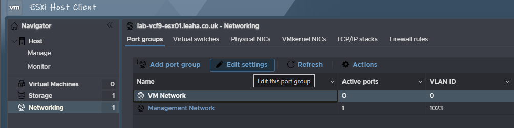
Log into the first host and click Networking
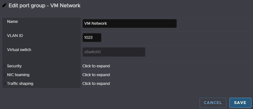
If you set a VLAN for the management VLAN and the management components are going on the same VLAN, which I recommend, we will need to edit the VM Network to set this VLAN, click the VM Network, then Edit Settings
Set the VLAN tag and click Save
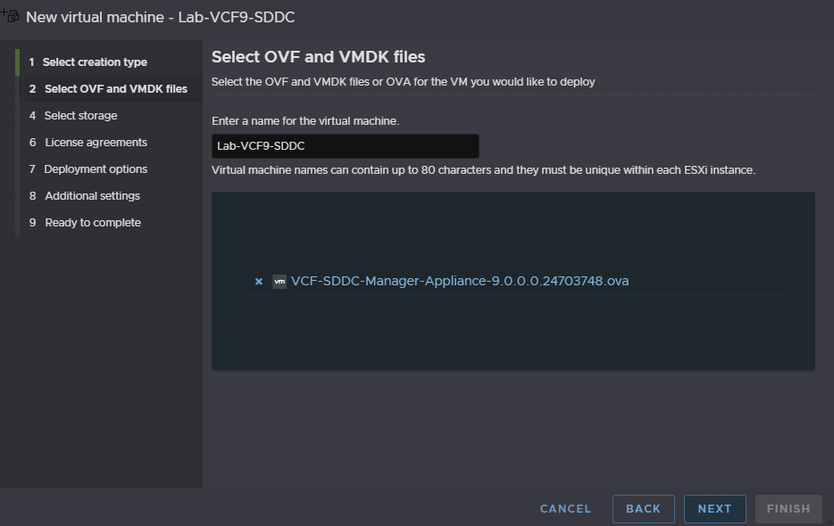
Now click Virtual Machines/Create / Register VM
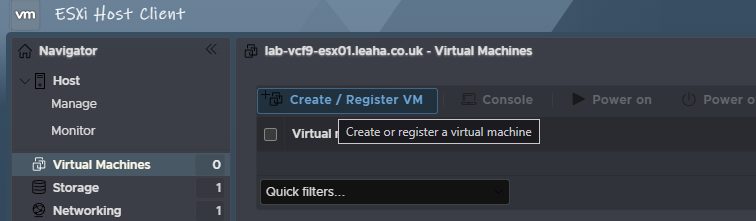
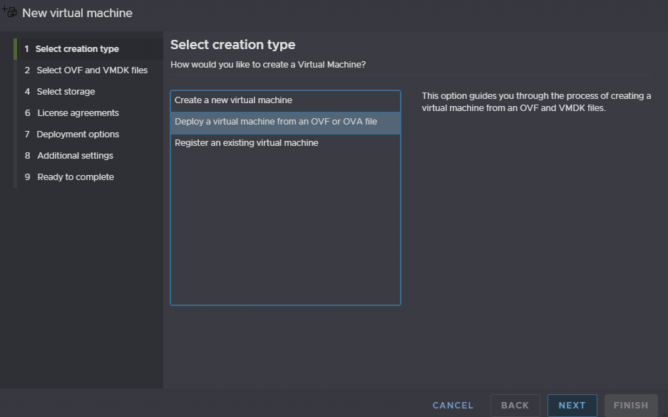
Click the second option to deploy a virtual machine from an OVF or OVA file and click Next
Enter a name, this will become the SDDC Manager later so name it for that, then click the box in the middle
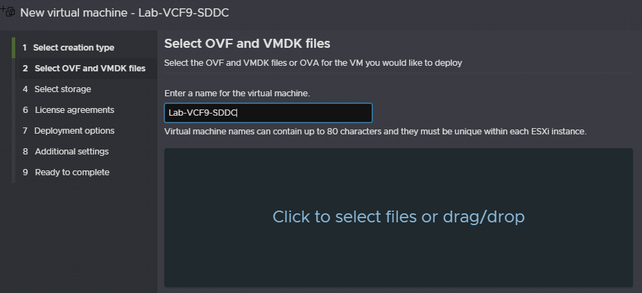
Find and double click the SDDC Manager appliance
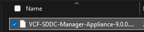
Then click Next
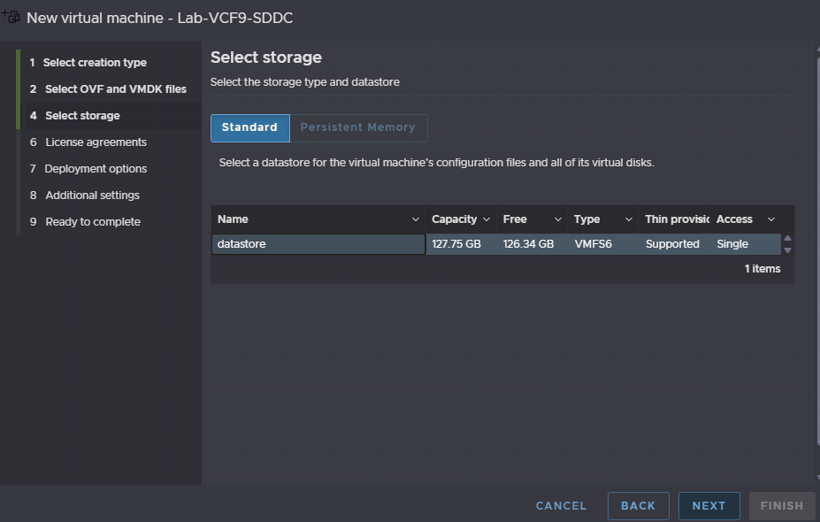
Select the install datastore which is create when ESX is installed, this uses leftover space on the boot device, and click Next
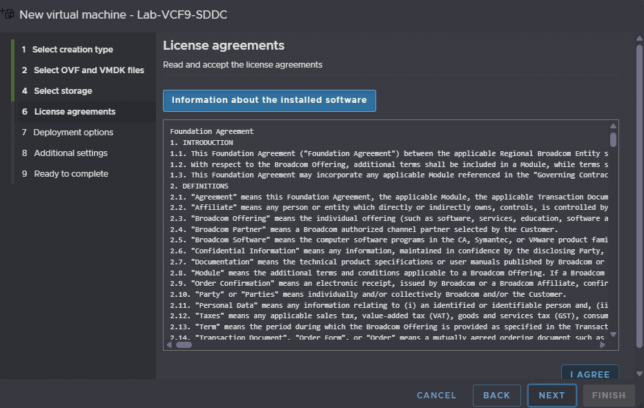
Click I Agree and then Next
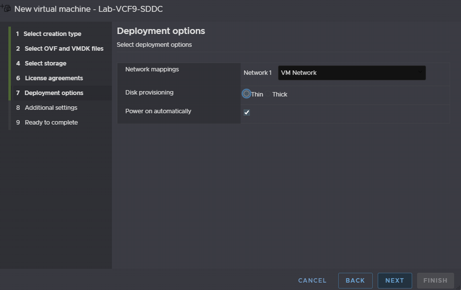
The network mapping should be on VM Network, provisioning needs to be thin, and the box to power the VM on automatically should be checked, then click Next
Under Application enter a root and local user password, these need to be 15 characters with the only special characters being !@#$%^&*
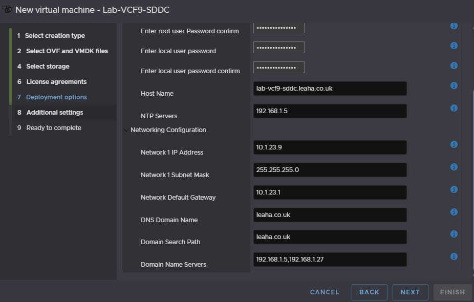
For the hostname enter the FQDN and for NTP add your NTP server
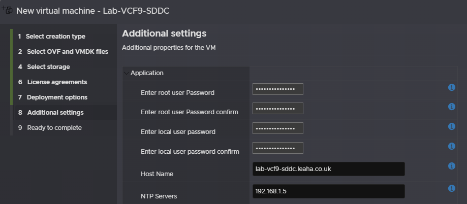
For the networking section, enter the SDDC Manager IP address, subnet mask, gateway, DNS domain and search domain path and DNS servers, comma separated, then click Next
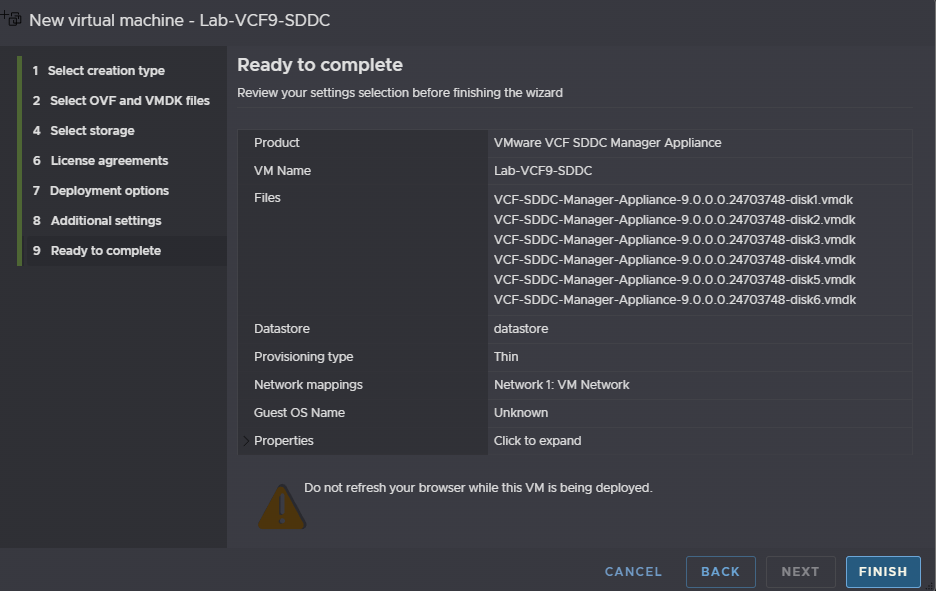
And click Finish
Do not refresh your page while this is deploying
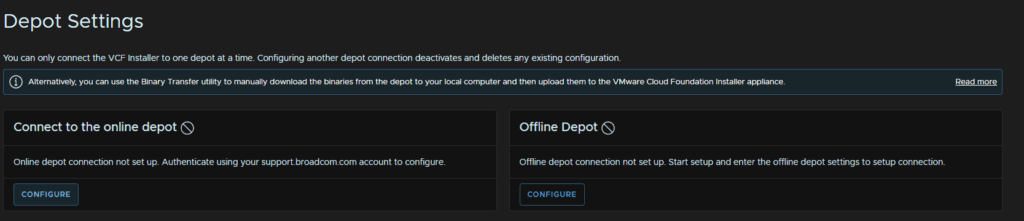
2.2 – Downloading Binaries
Now we have the appliance deployed we need to download all the software binaries, log into the VCF Installer on
https://fqdn
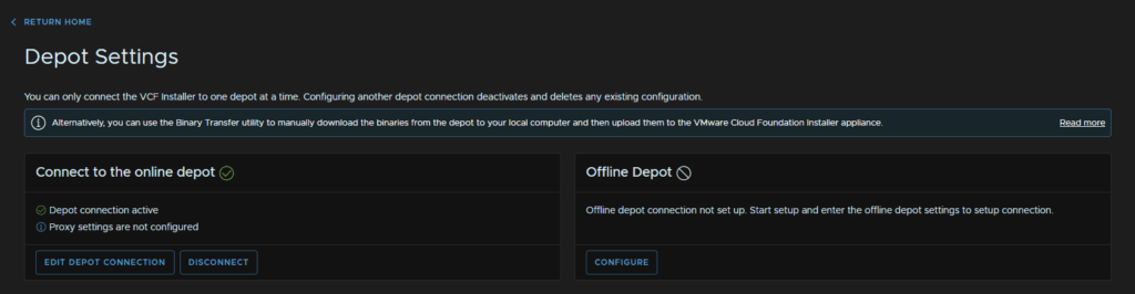
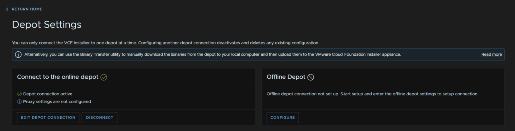
Then click Depot Settings And Binary Management
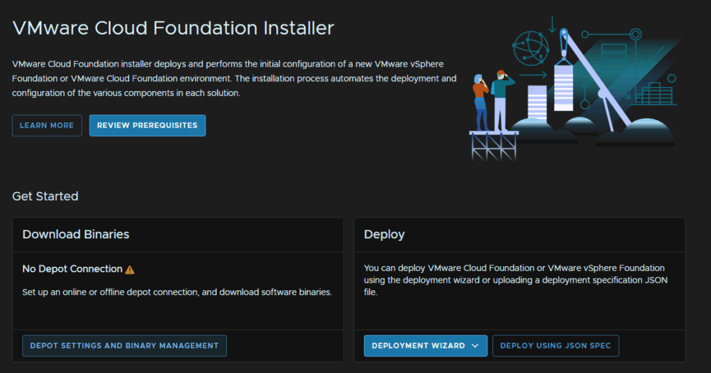
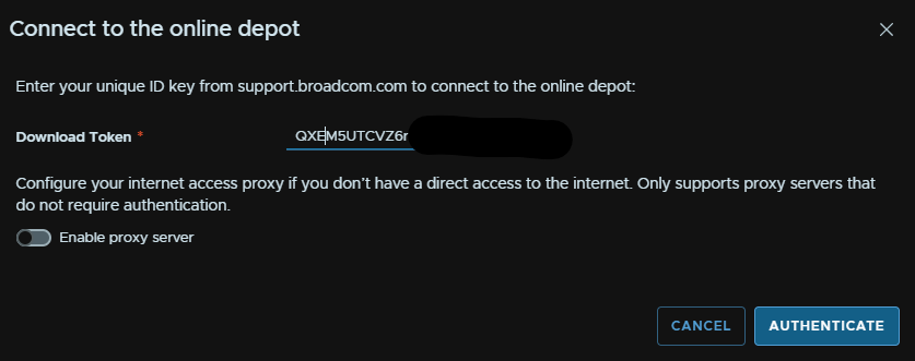
On the Connect To The Online Depot widget, click Configure
Enter your download token, you may need to enable the proxy server if you have one in your environment, and click Authenticate
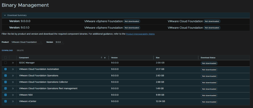
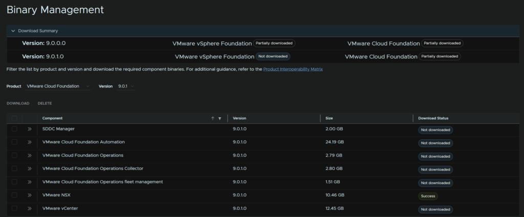
At the bottom, select your release version, I am doing 9.0.0.0, and select everything apart from the SDDC Manager and click Download
When its all done, it should look like this
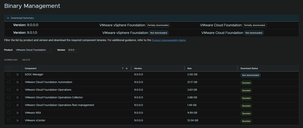
We can then click Return Home at the top left to get back to the main menu
2.3 – Starting And Existing Components
As we proceed through we will need to add various appliances, ensure all are DNS registered as you go through it before you finish the deployment
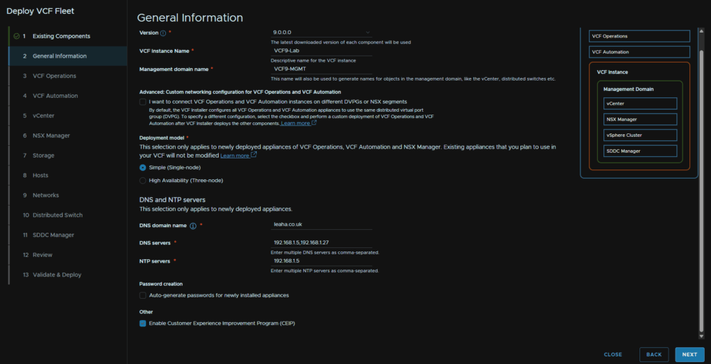
On the Deploy Widget, click Deployment Wizard/VMware Cloud Foundation
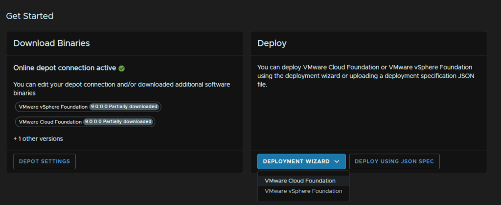
As this is a brand new install, select Deploy New VCF Fleet and click Continue
You would use the other option if you have a VCF fleet/instance, and want a separate SDDC manager to add to an Operations instance
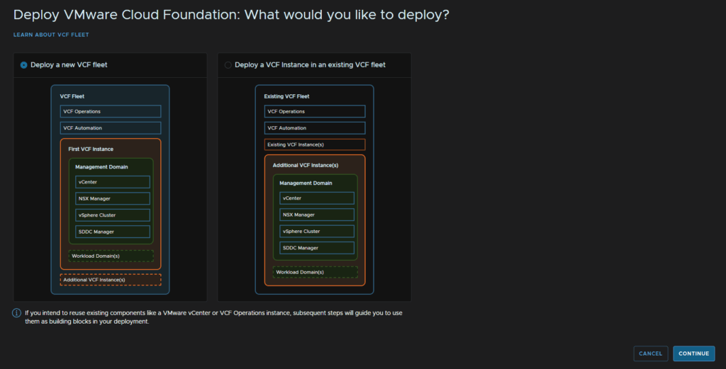
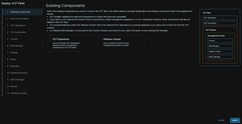
We dont have any existing components, so click Next
2.4 – General Information
Now we need to select our version, as I downloaded 9.0.0.0, thats what I selected, then enter a name for the VCF9 Instance, you can use the SDDC Manager hostname, or a different name, enter a management domain name, you can use a name, like I have, for whats being run in this domain, or the vCenter name
We can leave the advanced check box unchecked
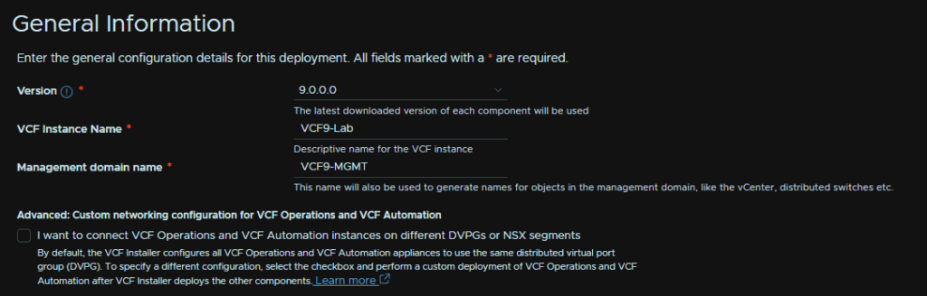
For deployment model, simple works best for most environments, the only thing you likely want as a multi node setup is NSX, but we can set this later
Then add your domain name, DNS servers, comma separated and NTP servers, also comma separated
Password create I am opting to do manually
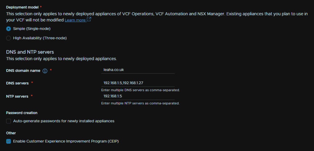
Then click Next
2.5 – VCF Operations
For VCF Operations, here is the sizing chart so you can line it up for your environment, Extra Small should not be used in production
| Small | Medium | Large | Extra Large | |
| Single Node Max Objects | 10,000 | 30,000 | 44,000 | 100,000 |
| Single Node Max Metrics | 1,600,000 | 5,000,000 | 8,000,000 | 20,000,000 |
| Max Nodes In A Cluster | 2 | 8 | 16 | 12 |
| Cluster Max Objects | 12,000 | 136,000 | 576,000 | 1,056,000 |
| Cluster Max Metrics | 2,800,000 | 32,000,000 | 81,600,000 | 126,000,000 |
| vCPU | 4 | 8 | 16 | 24 |
| RAM | 16 | 32 | 48 | 128 |
We need to select our Operations node size, then add the FQDN, ensure this is registered in DNS, then add an admin and root passwords meeting the requirements at the start of this section
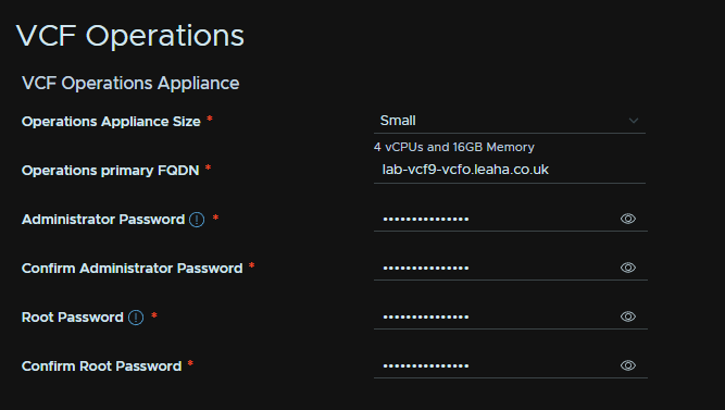
The fleet management appliance needs an FQDN, registered in DNS, then an admin and root password meeting the requirements
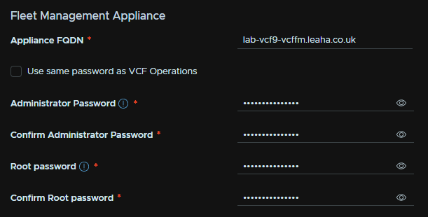
Lastly the collector for operations needs a DNS registered FQDN and a root password meeting the requirements
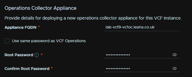
Then click Next in the bottom right
2.6 – VCF Automation
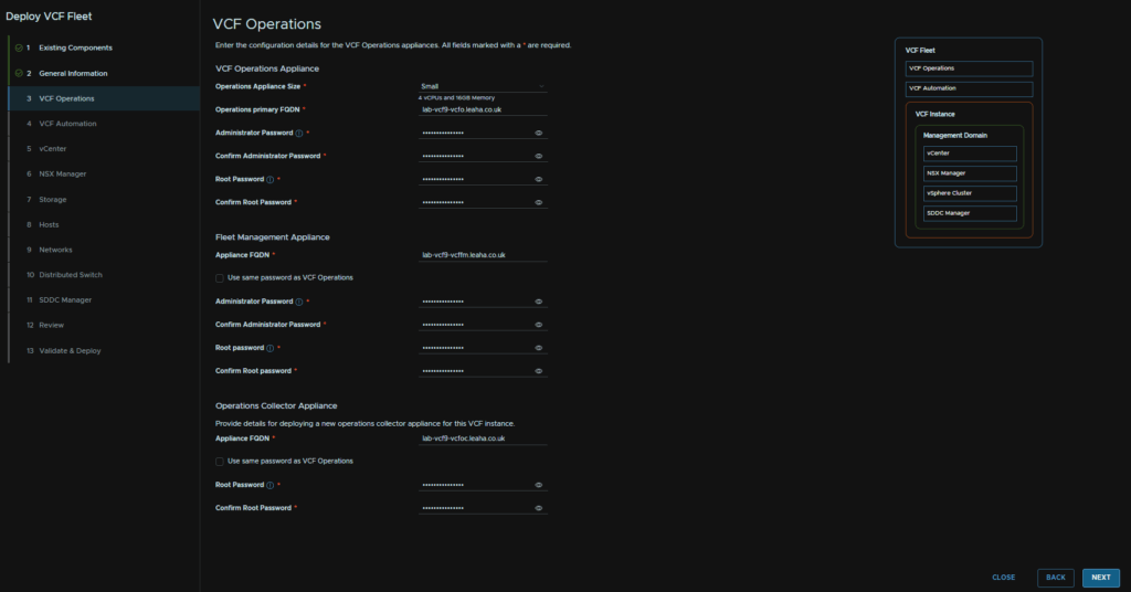
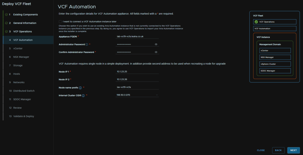
For VCF Automation, we need a DNS registered FQDN, an administrator password meeting the requirements
Then we needs two node IPs, these want to be additional IPs
Eg, my FQDN, lab-vcf9-vcfa.leaha.co.uk is 10.1.23.24, and my node IPs are 10.1.23.25 and 10.1.23.26
Add a node name prefix, and leave the internal cluster CIDR at the stock value and click Next
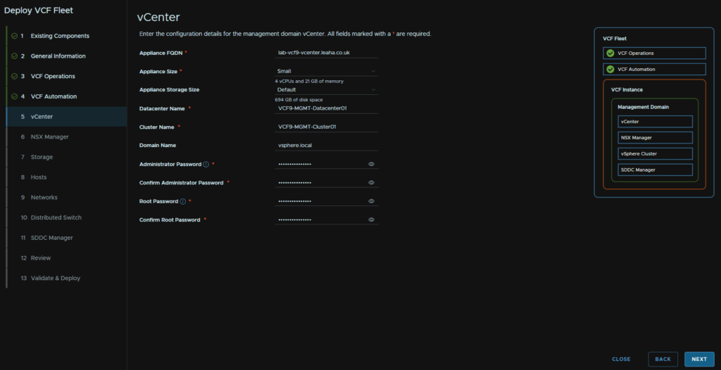
2.7 – vCenter
The vCenter sizing has these requirements, tiny should only be used in labs and POCs, otherwise select the size that meets your requirements
| Small | Medium | Large | Extra Large | |
| Host/VM Capacity | 100/1,000 | 400/4,000 | 1,000/4,000 | 2,000/35,000 |
| vCPU | 4 | 8 | 16 | 24 |
| RAM | 21 | 30 | 39 | 58 |
We then need a DNS registered vCenter FQDN, select the appliance size, storage size, default is generally fine here, then we need a datacenter and cluster name, vSphere domain name, vsphere.local is fine here and can be left at the default, then we need a password for the [email protected] account and root accounts meeting the requirements
Then click Next
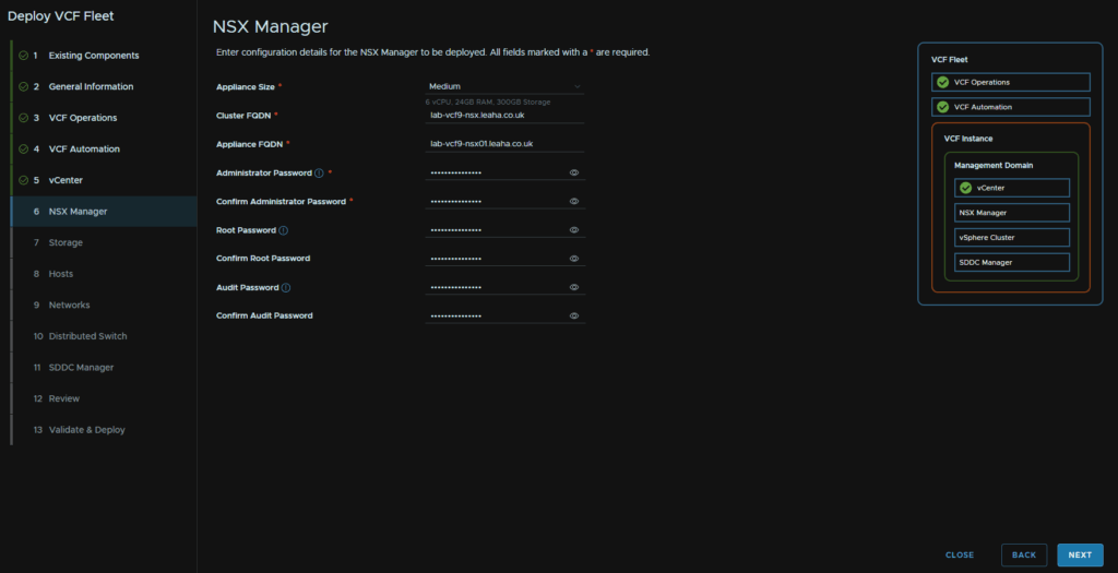
2.8 – NSX Manager
Sizing wise, VCF has the following, this is from VCF 5.1 as VCF 9 doesnt give host numbers
| Medium | Large | |
| Host Maximum | 128 | 1,024 |
| vCPU | 6 | 12 |
| RAM | 24 | 48 |
| Maxium Compute Managers | 2 | 16 |
For NSX we need to set the manager size, Medium is generally fine and what you likely need, we then need a cluster and node FQDN, both DNS registered, and an admin, root and audit password meeting the requirements
Then click Next
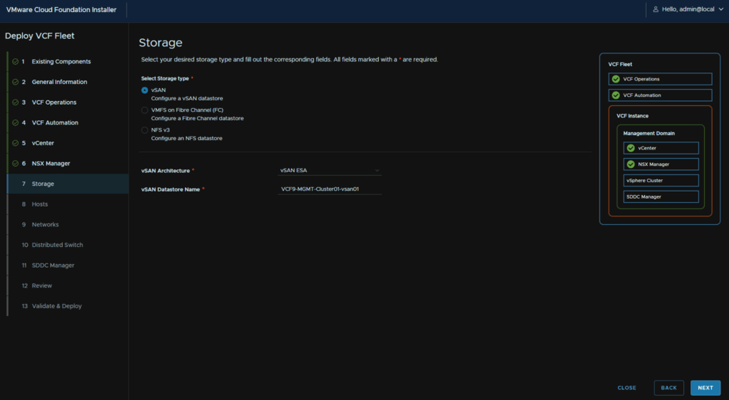
2.9 – Storage
We need to select our storage type, we can do VMFS on Fibre Channel, NFS v3, and vSAN, which we will be using
Select the vSAN architecture, you likely want ESA, which requires NVMe disks and HCL compatibility, but you can use the OSA architecture with Cache and Capacity disks
Name the datastore and click Next
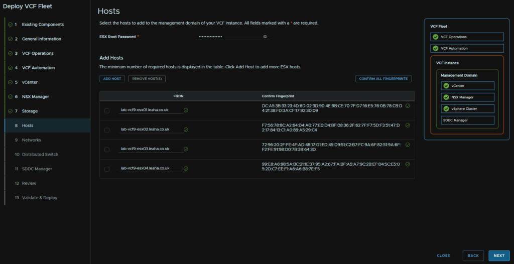
2.10 – Hosts
We then need to add the password for the ESX hosts, they should all be the same, add our hosts, I have 4, add the FQDN, then click Add for each host
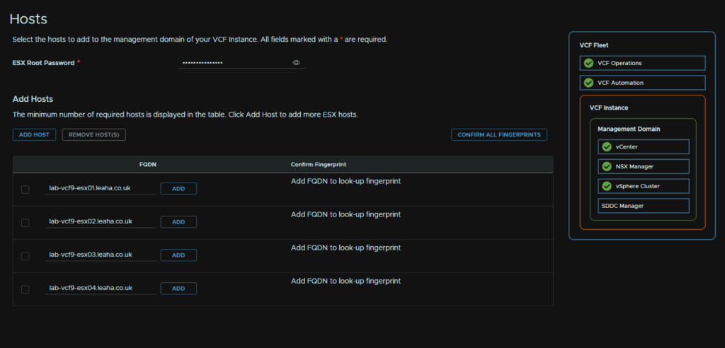
This will grab the thumbprint, and we can click Confirm
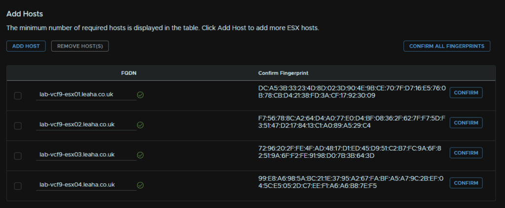
Then click Next
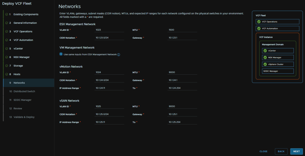
2.11 – Networks
For networks we need our ESX management network, including the VLAN, leave the default 1500 MTU, CIDR and gateway
I am using the same VM for the VM management so I checked that box, but if you wanted a separate one you can add those details
Then we need vMotion and vSAN networks, and the ports should have an MTU of 9216 for this, at the physical switch level, normally these are isolated non routable networks, but a gateway is needed, so we can just enter an IP here
We need the VLAN, CIDR, gateway, my lab has this gateway to make troubleshooting easier, but you can put a placeholder IP in, and an IP range to assign to hosts, on a /24 network I like 11-254
Then click Next
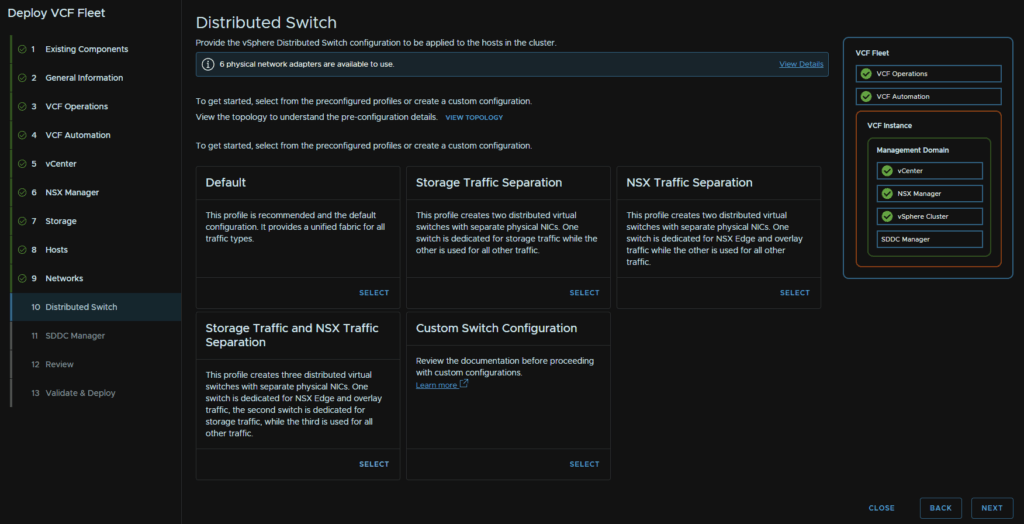
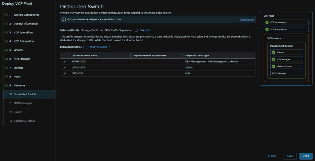
2.12 – Distributed Switches
How we do the VDS depends on our NIC config, you should have 4 or 6 NICs at 10Gb all configured the same at the switch side
For a 4 NIC host setup, select Storage Traffic Separation, for a 6 NIC host setup like mine, select Storage Traffic And NSX Traffic Separation
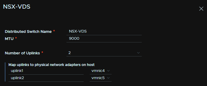
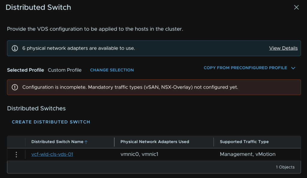
We will then get this wizard, we can use the arrows on the VDS to edit them
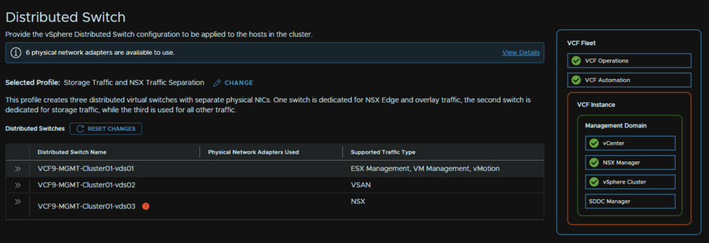
We can then name the VDS, the uplinks here want to contain the vmnic used in management at the moment, if you have only 2 physical NIC cards, this is the one which should have two uplinks from a single card, while loosing vCenter, ESX Management and vMotion isnt ideal, it isnt a P1 incident compared to loosing vSAN or VM traffic with NSX
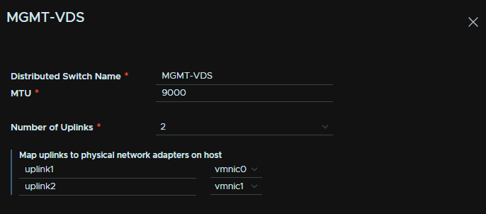
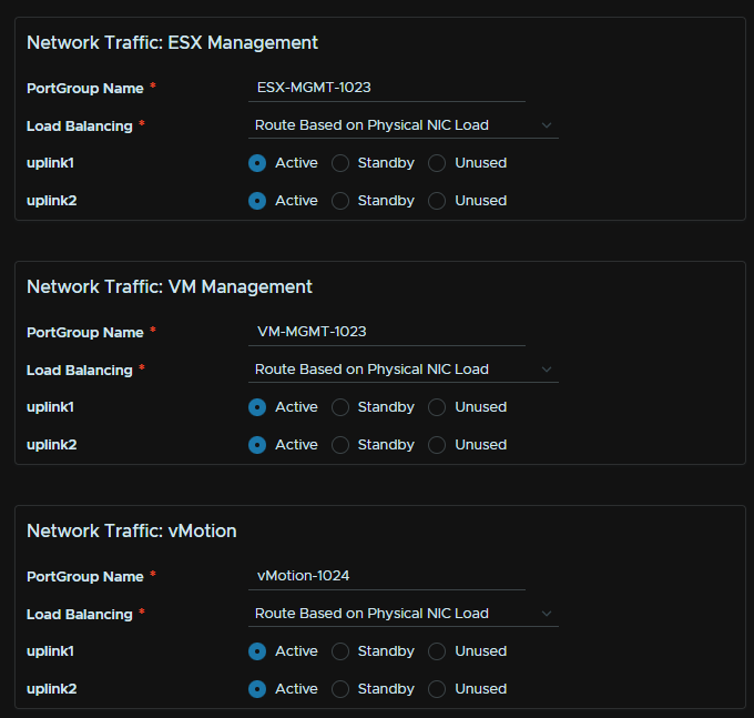
We then need to name the port groups, the remaining settings are fine at the default
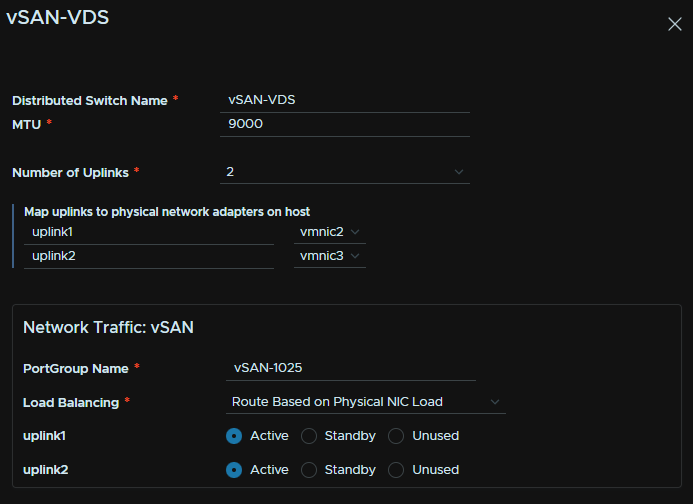
We then need to repeat for the vSAN VDS naming it, adding our uplinks, if you have 2 or more cards these uplinks should also span both physical cards, and name the port group
We then need to edit the last VDS and name it, this has out network traffic, and should use the remaining ports, if you have only two physical NIC cards this should use ports on both cards, 1 on each
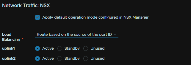
Leave this on the default
We then need the transport zone information, name the transport zone, I named it after the management domain name, add the host TEP VLAN ID, IP assignment should be IP Pool, then name the pool, add the CIDR, IP start/end range and the gateway, this gateway must exist
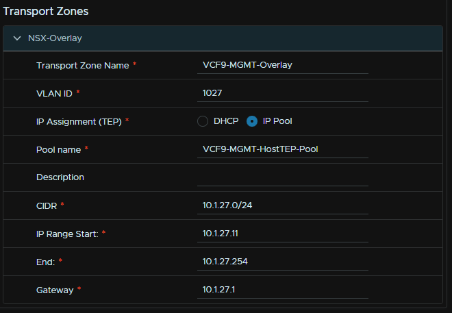
Then click Next
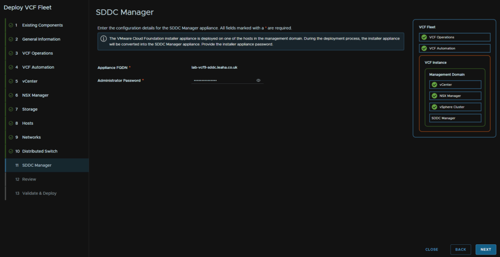
2.13 – SDDC Manager And Progress
Enter the SDDC Manager admin password, this should be the same as the admin password for the VCF installer and click Next
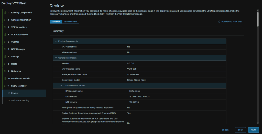
Then click Next for the validation
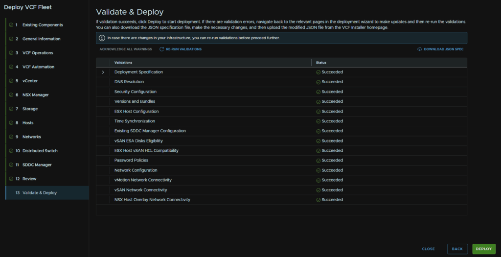
You’ll need to address any issues you get, though mine ran without any and looks like this, when you are ready, click Deploy
We’ll then get a different menu that looks like this where we can track our progress
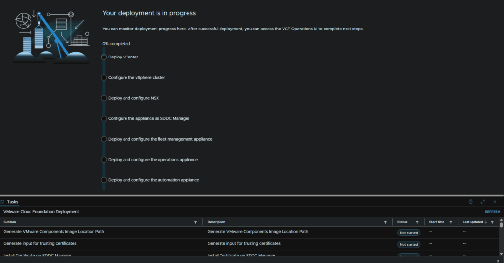
When thats done it will look like this, and we can start deploying the remaining components
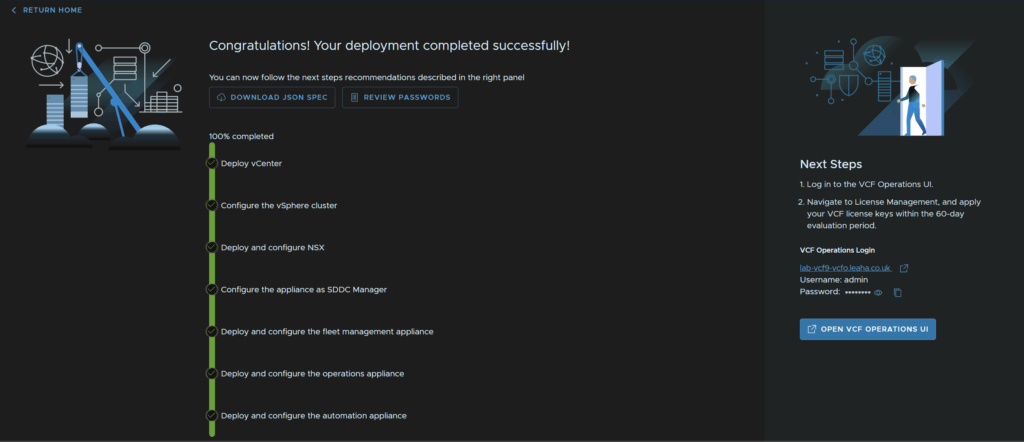
We can follow the link on the right to open VCF Operations for the next Steps
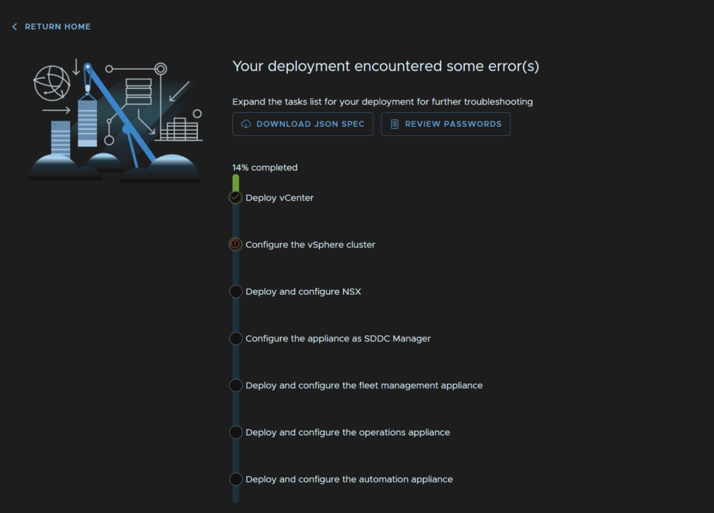
2.14 – Errors
2.14.1 – Product Image Validation Issues
This seems to be a bug when deploying an older version, this shouldnt be an issue when deploying the latest, but I got a few validation issues from the latest binaries not being downloaded, even though it wasnt the deployment issue
The error for NSX I have no idea why I got that, however it did deploy NSX 9.0.1, vCenter errored the same, but after deployment, it still needed the package downloading, but is on the correct, 9.0.0 version I selected
I got this error for a failure to validate the NSX 9.0.1 image, which was odd as I selected 9.0.0 as the install version

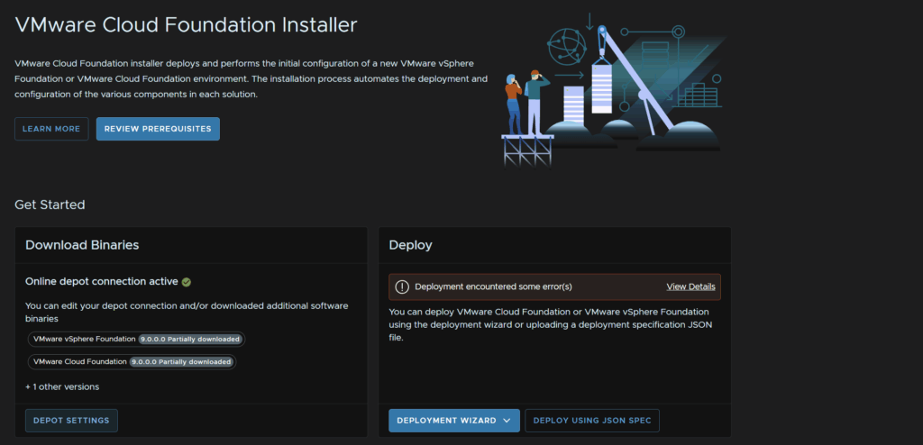
We can click Return To Home in the top left
Then click Depot Settings
I then selected the 9.0.1 release, checked NSX and clicked Download
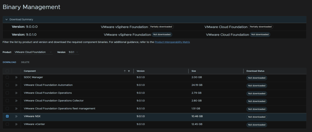
Which shows like this when its done
Click Return Home in the top left
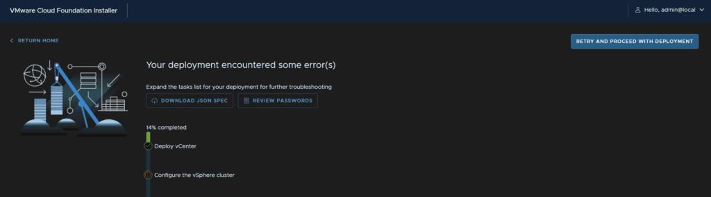
On the Deploy widget, click View Details on the error
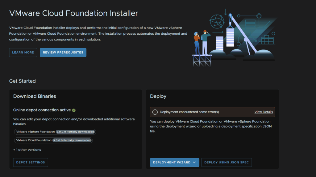
And click Retry And Proceed With Deployment
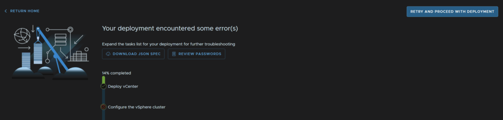
I also got this for the vCenter download, I did the same thing and downloaded the 9.0.1 version, this was a bit odd given it already deployed vCenter 9.0.0

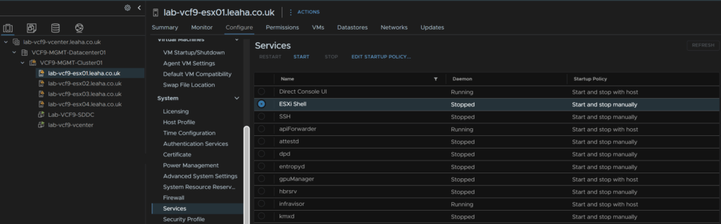
2.14.2 – Management NIC Migration Failure
This only seems to happen for virtual ESX hosts used in labs, but the error looks like this

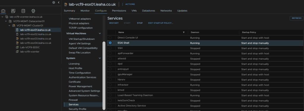
We need SSH and the ESX Shell, to enable this, in vCenter select the host, they should all be added, then click Configure/System/Services, select ESXi Shell and click Start
Then open up the ESX console and press Alt + F1 to access the shell and login
Then run
esxcli network ip interface list | lessWe should see vmk0, the management interface
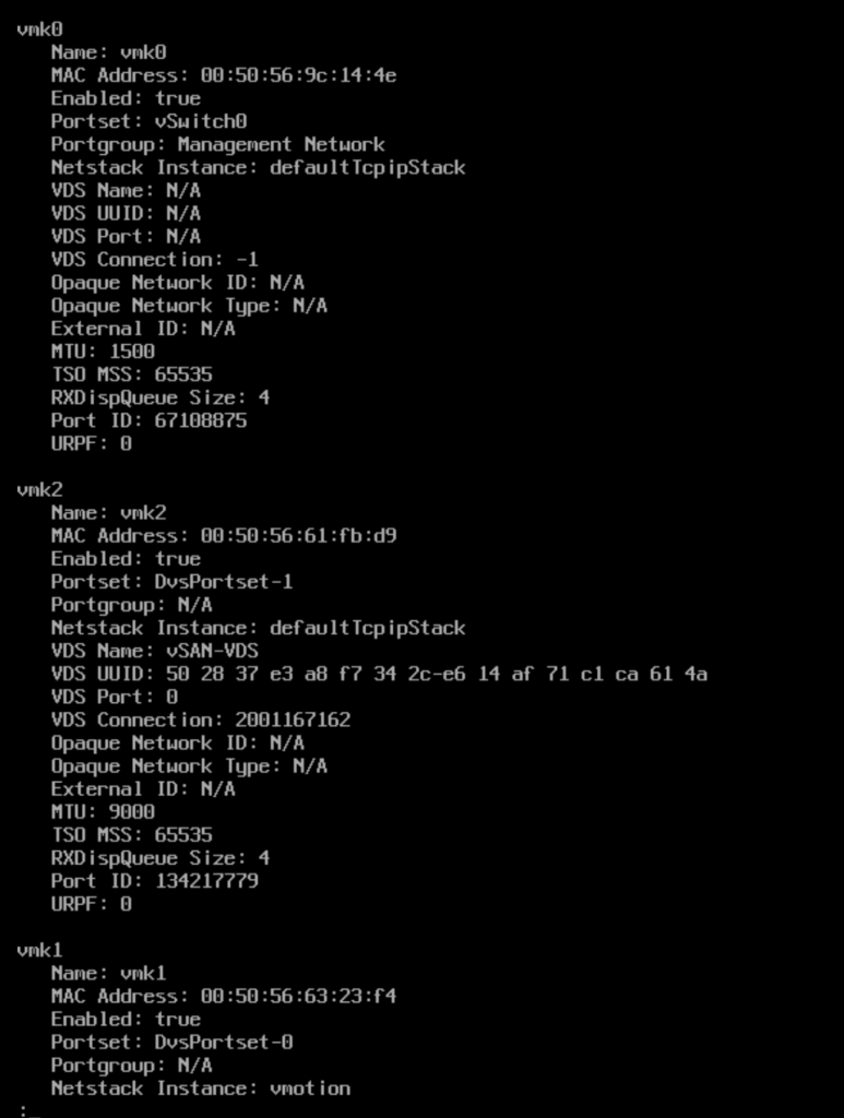
We need to note the portgroup, which should be ‘Management Network’
We can press ‘q’ to exit this
Now remove the interface with
esxcli network ip interface remove –-interface-name=vmk0Then recreate it with
esxcli network ip interface add -–interface-name=vmk0 -p "Management Network"We can press Alt + F2 to switch back to the DCUI, press F2 and login as root
Press Enter on Configure Management Network
Press Enter on IPv4 Configuration

Use the third option to set a static IP and enter the details setup at the ESX deployment stage and press Enter

Then press Escape
And press Y here
Then repeat for the remaining hosts
Head back to the host in vSphere and disable the ESXi shell service from Configure/System/Services, click ESXi Shell and click Stop
Lastly, back in the VCF Installer, in the top right click Retry And Proceed With Deployment
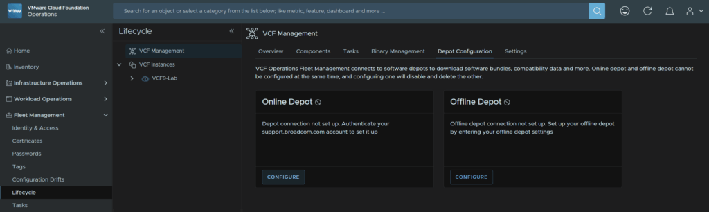
3 – Configuring Fleet Management
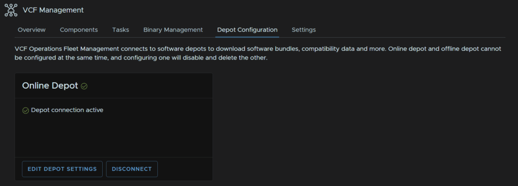
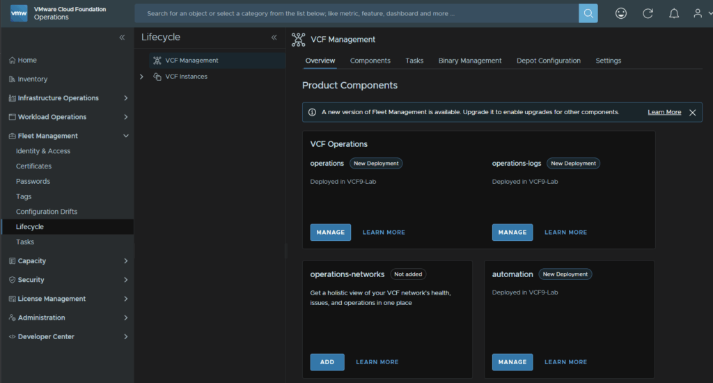
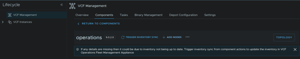
Before we can install the remaining components we need to configure the fleet management depot, to do this, from VCF Operations, head to Fleet Management/Lifecycle/VCF Management/Depot Configuration and click Configure on the Online Depot widget
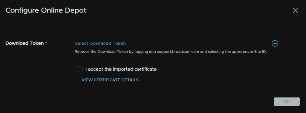
Click the + icon
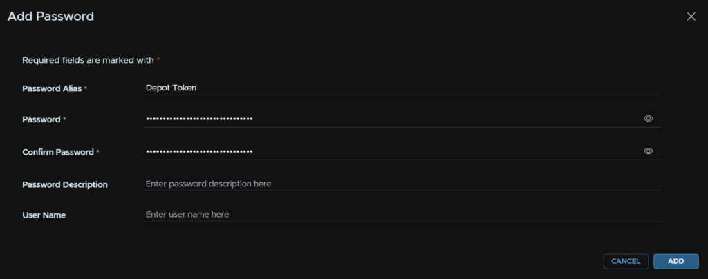
Give the token a name, and in the password fields, enter the token, then click Add
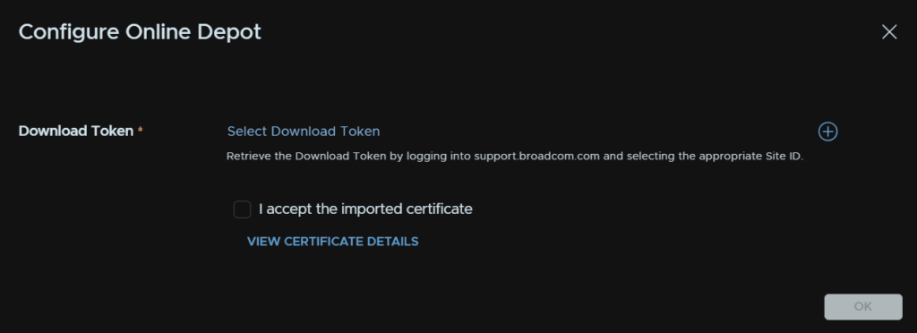
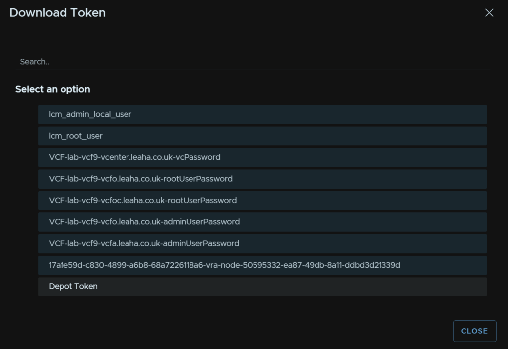
Now click Select Download Token
Click the newly created credential
Check the box to accept the depot certificate and click ok
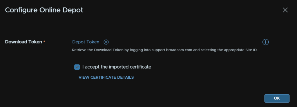
It should then look like this
We then need to download our additional appliances, as I am installing VCF 9.0.0, I selected that version, and I am installing both Operations Networks and Operations Logs, select the ones for your version and click Download
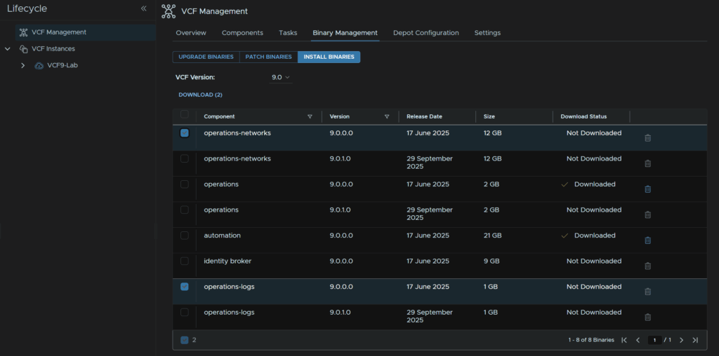
I did find it can be very odd and delete the download after so it took me a few downloads to get it to stick
4 – VCF Operations For Logs
We’ll need an FQDN registered in DNS for this and we need a root/admin password ready using the requirements from earlier
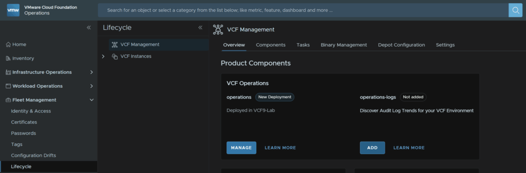
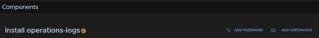
To deploy VCF Operations For Logs, in VCF Operations, head to Fleet Management/Lifecycle/VCF Management/Overview, and under operations-logs, click Add
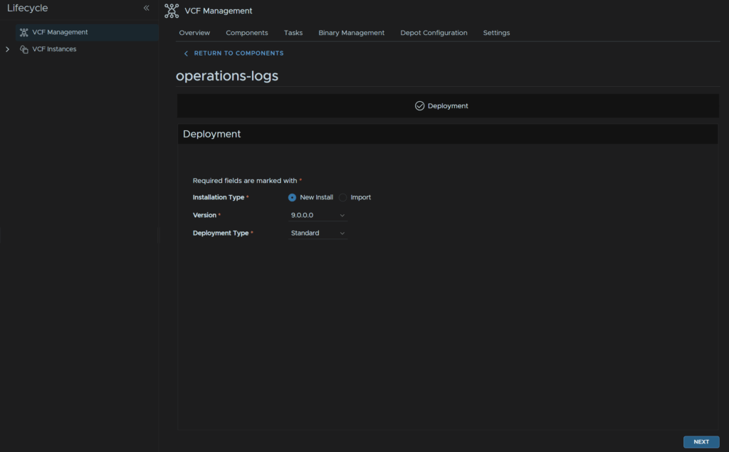
Select the version, this will match the downloaded binary, and click Next
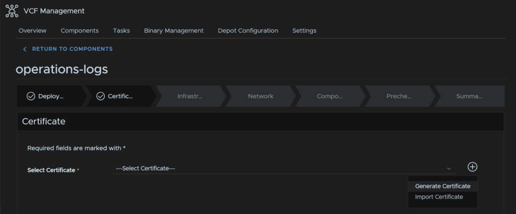
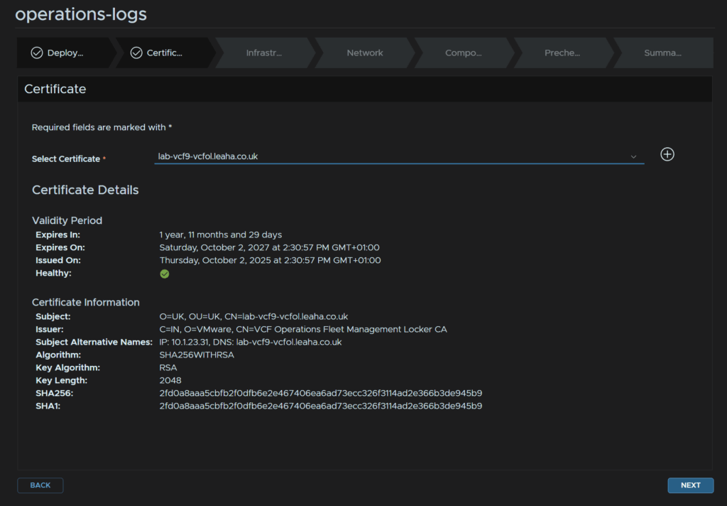
Click on the + to add a new certificate then click Generate Certificate
You can import them if you are using an on prem CA
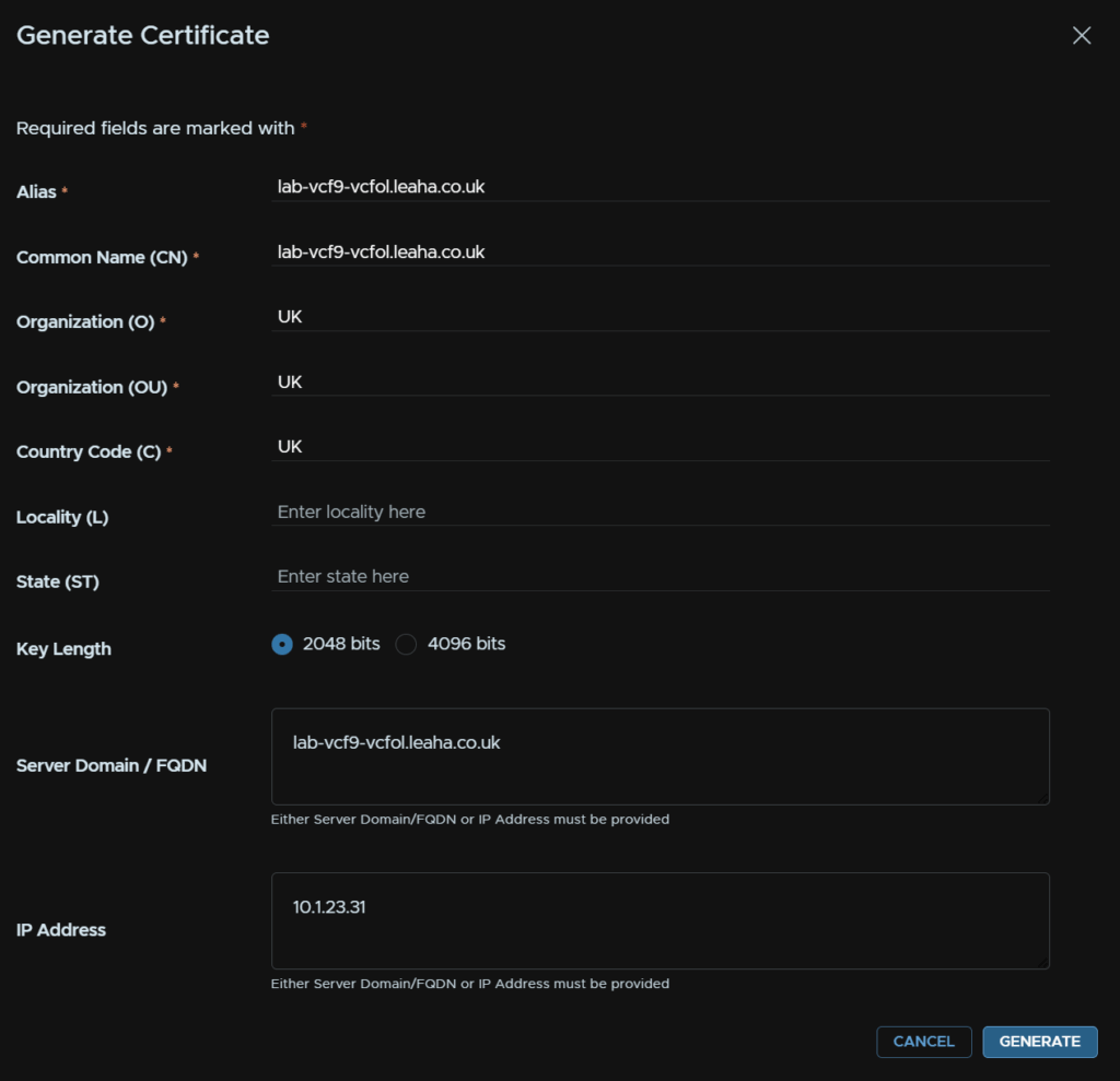
For the Alias and CN enter the server FQDN, O/OU/C dont really matter as its self signed, in the FQDN box add the FQDN and add the IP into the IP Address box and click Generate
Select the certificate from the drop down and click Next
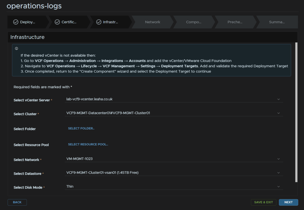
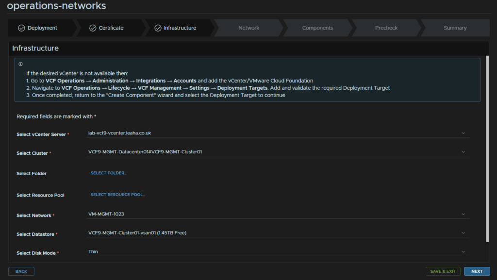
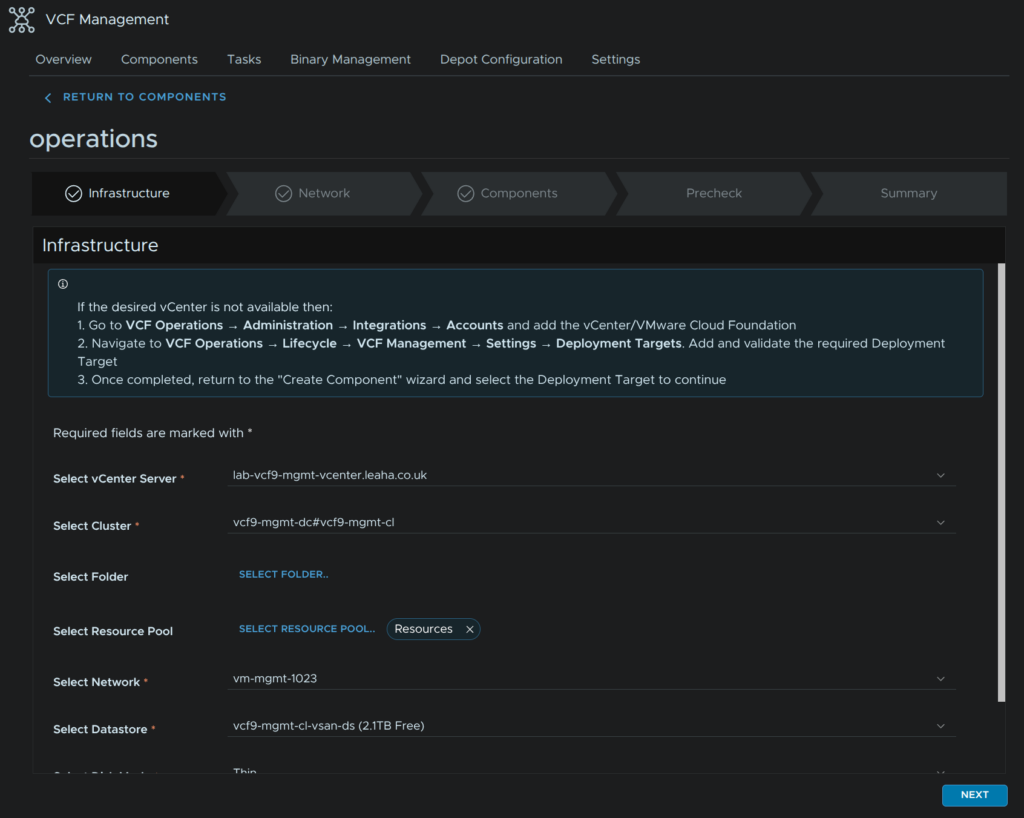
Select your vCenter and cluster, optionally select a folder/resource pool, select the VM Management port group, the one Operations is on, select a datastore, in my case the vSAN datastore, select the disk policy, as mine is vSAN it doesnt really matter, but if you used Fibre Channel or NFSv3 during the deployment you want think
Then click Next
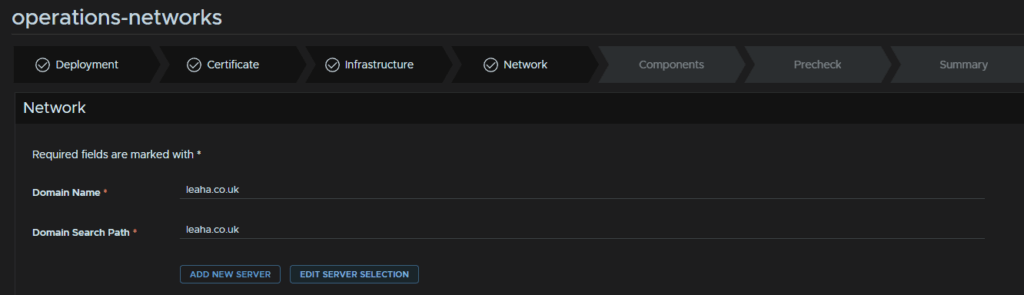
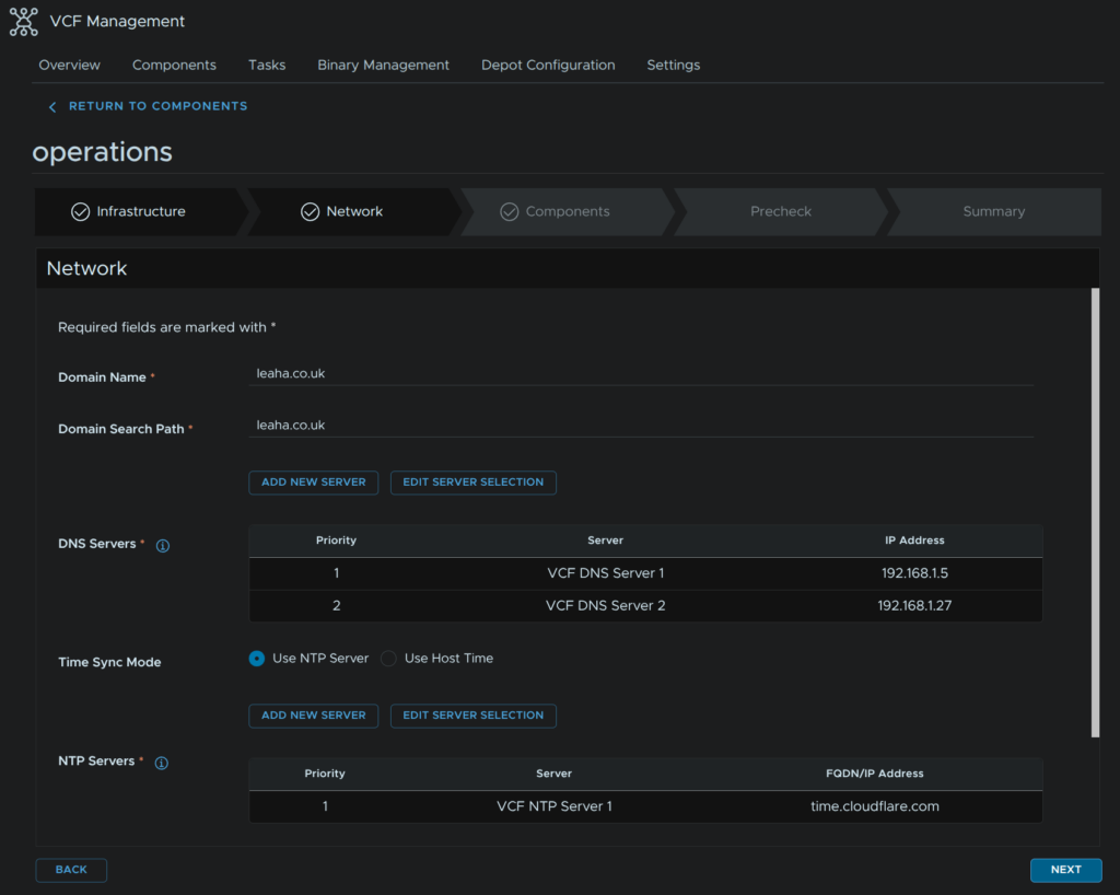
For Network, add your domain and search domain, then click Edit Server Selection for DNS servers
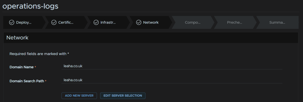
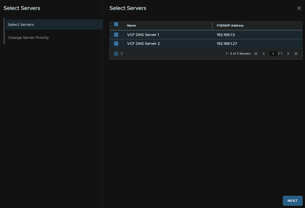
Select both DNS servers and click Next

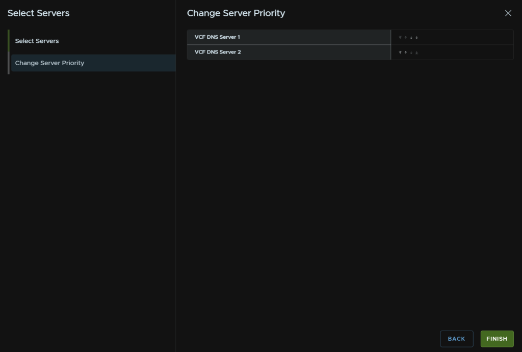
Then click Finish

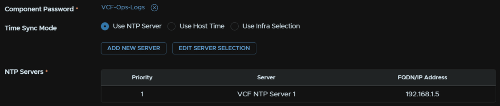
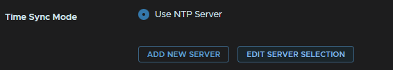
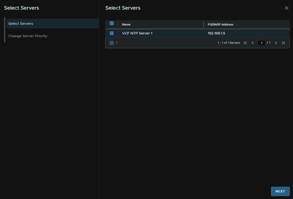
For Time Sync Mode, click Use NTP Server, then click Edit Server Selection

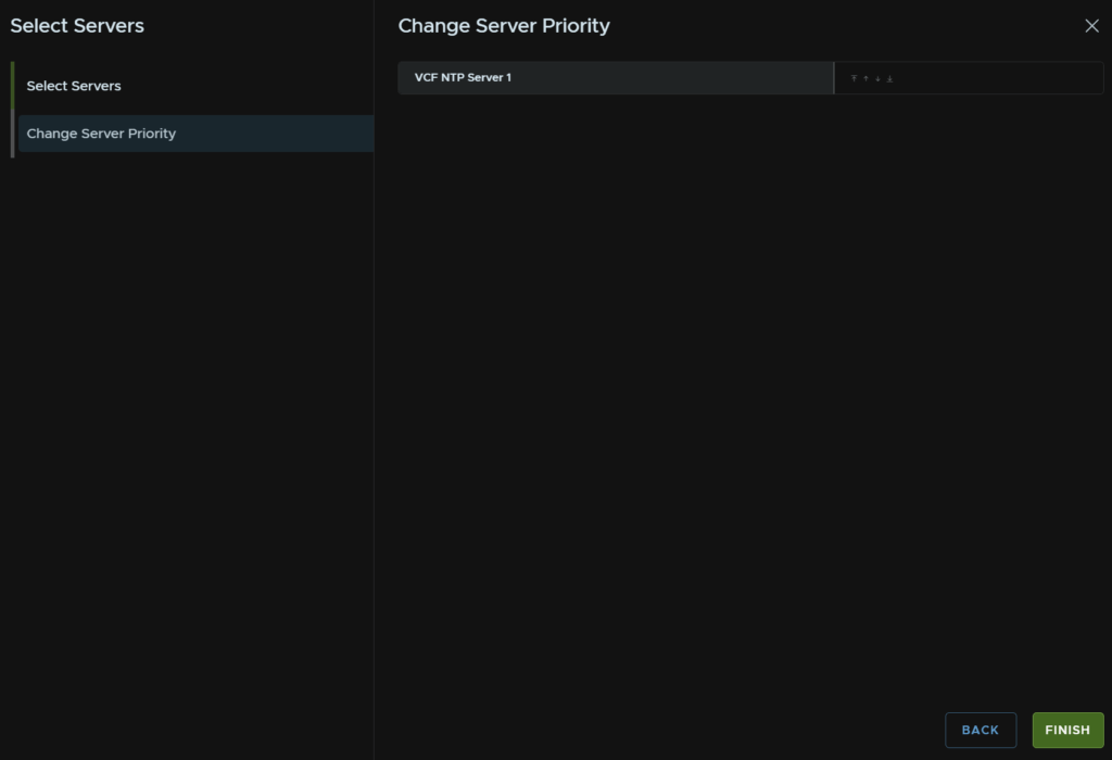
Select the NTP server, you may have a second from the VCF Installer, then click Next

And click Finish

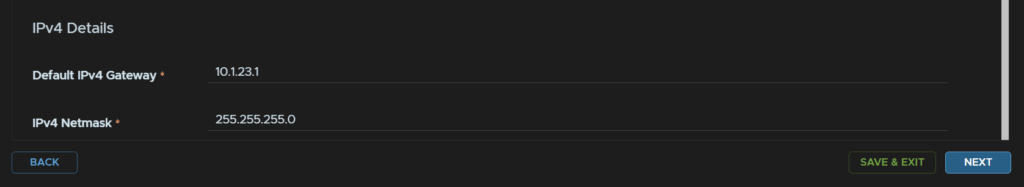
And enter the IPv4 gateway and subnet mask, then click Next
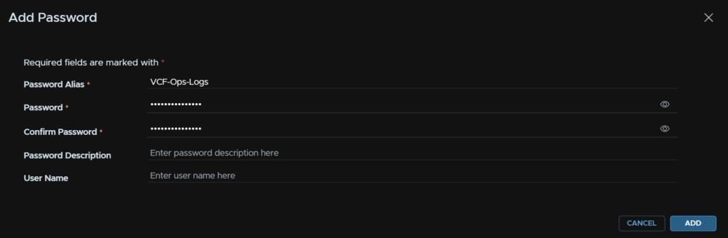
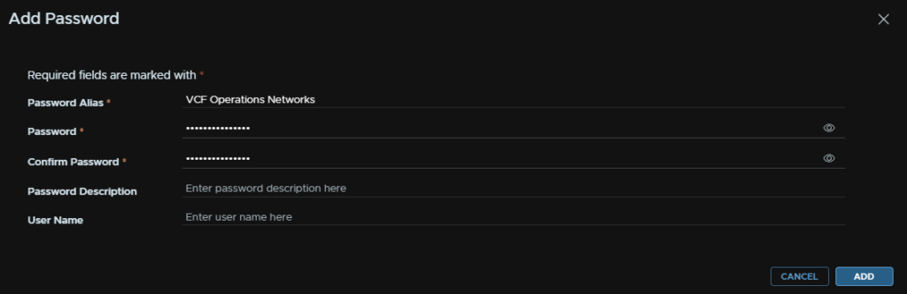
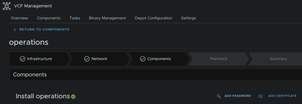
Click Add Password on the right
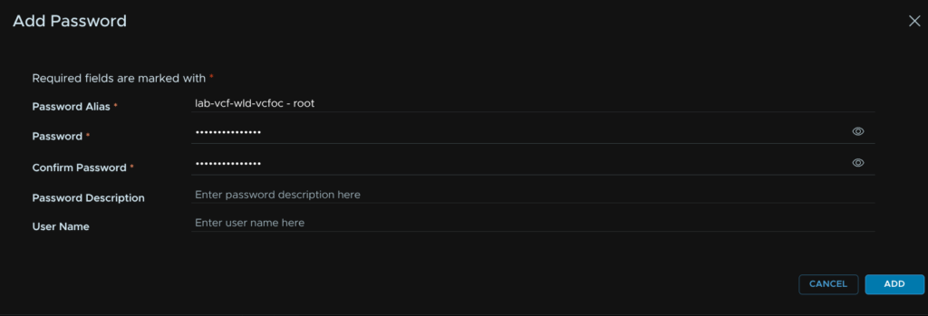
Enter an alias and the the password, this will be both the admin and root passwords
Then click Add
We need to select a size, small, medium and large are all we can deploy, as we are doing single node clusters we wont be scaling out
There are larger sizes if needed though these really only aim to solve querying issues so if you need bigger than large you will want to go down the clustered route for this
| Small | Medium | Large | |
| Log Ingestion Rate | 30GB/Day | 75GB/Day | 225GB/Day |
| IOPs | 500 | 1,000 | 1,500 |
| Syslog Connections | 100 | 250 | 750 |
| Events/Second | 2,000 | 5,000 | 15,000 |
| vCPU | 4 | 8 | 16 |
| RAM | 8 | 16 | 32 |
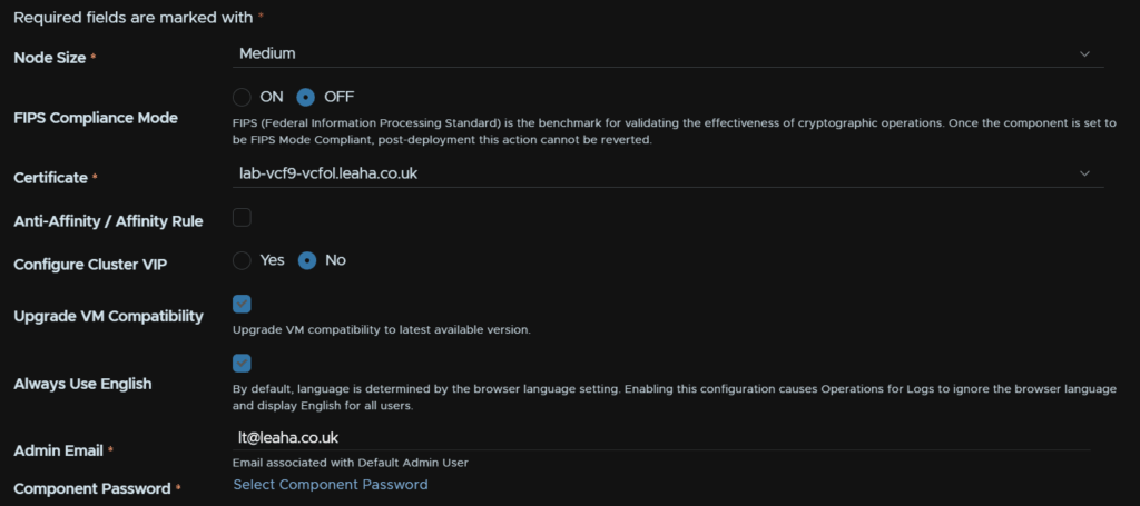
Select the node size, Medium will be enough for smaller environments, but you may need large
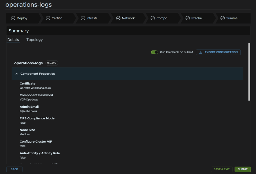
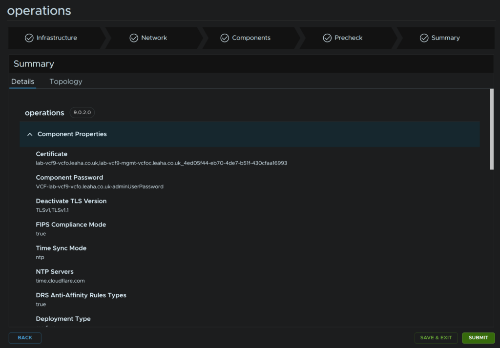
Enable FIPS if needed, the certificate will be auto populated, we can select no on the cluster VIP as I wont be using a cluster, check the box to upgrade the VM compatibility, check the box to always use English, add an admin email and click Select Component Password
We can always scale out if you need a clustered deployment or a large size at a later date
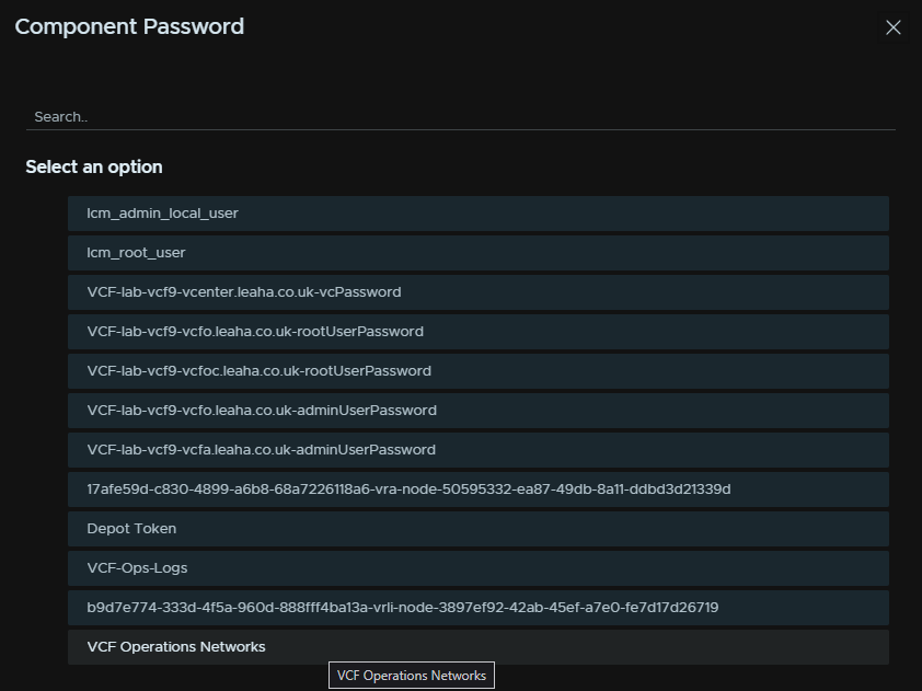
Click the password you created earlier
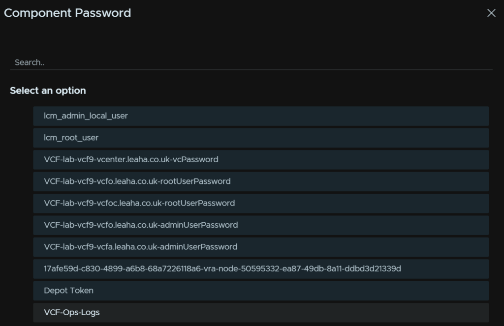
It should show here, and NTP should be pre configured
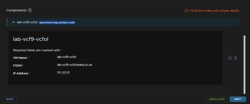
Enter the VM name, FQDN and IP address and click Next
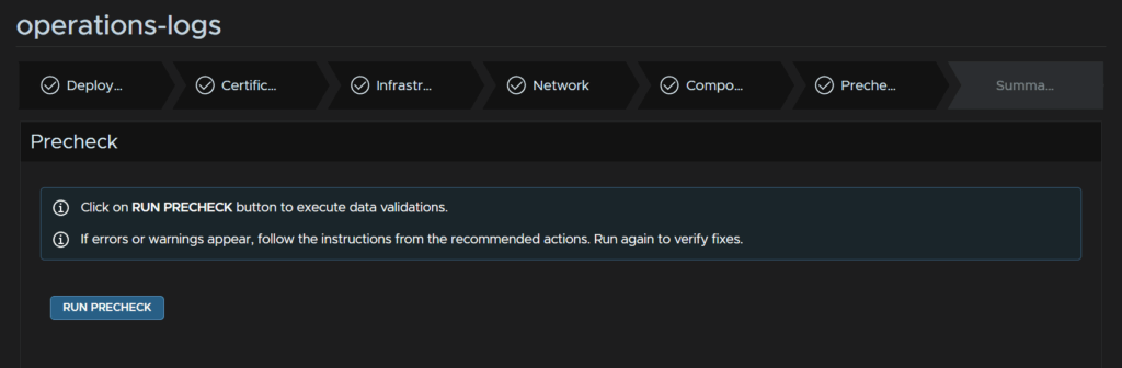
Click Run Pre Check
Address any warnings that crop up, I didnt get any, when its all green, click Next
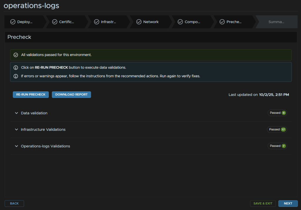
And when you are ready click Submit
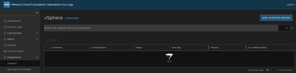
This doesnt register the vCenter directly into VCF Ops For Logs as a source, this means while all logs are coming in, it will be stuck in evaluation mode
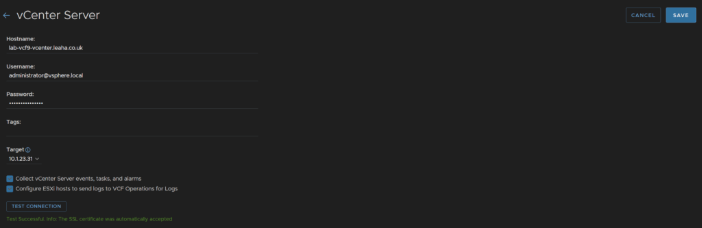
In the VCF Ops For Logs GUI click Integrations/vSphere and click Add vCenter Server
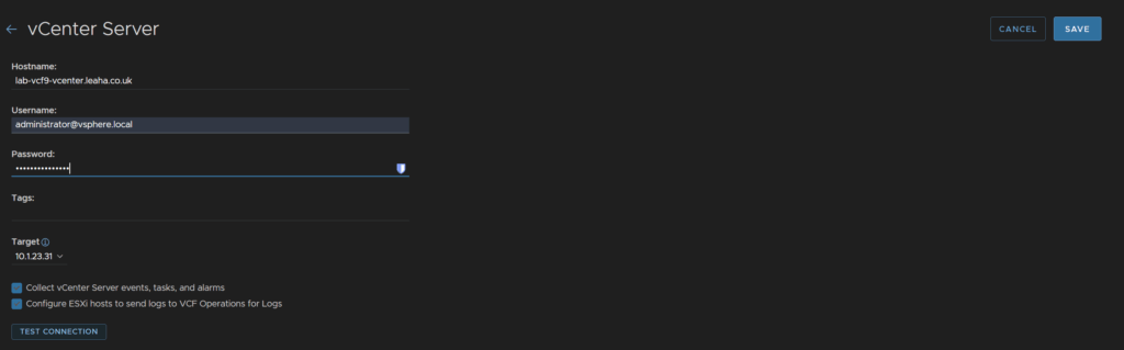
Enter your hostname for the vCenter and an administrator account, I recommend a service account, but I am using the default administrator account, I changed my SSO domain from vsphere.local to leaha.co.uk, so thats why its different
Select the target from the drop down, which is the Log server, make sure both boxes are checked and click Test Connection
Click Accept on the SSL certificate
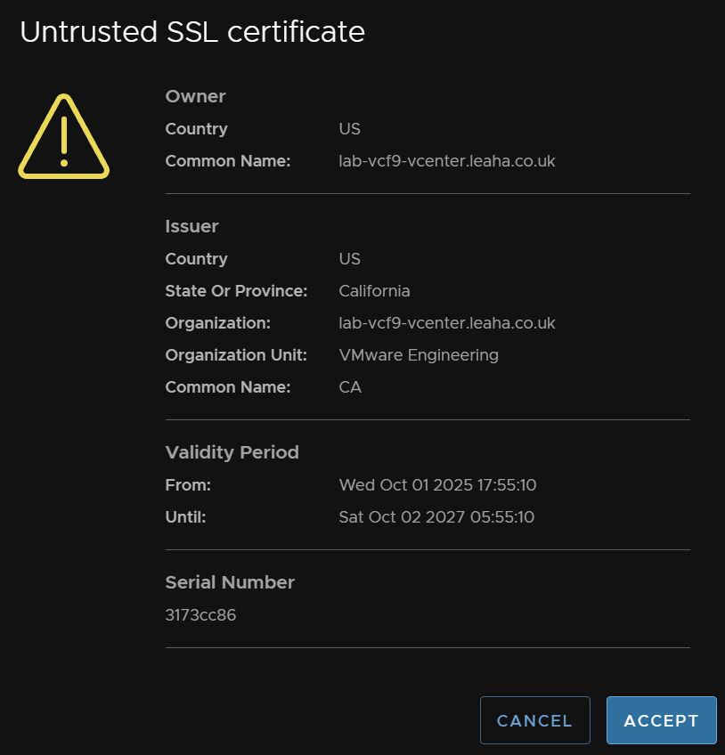
Then click Save
This removes the evaluation licensing mode from the server when we setup licensing in VCF Ops later
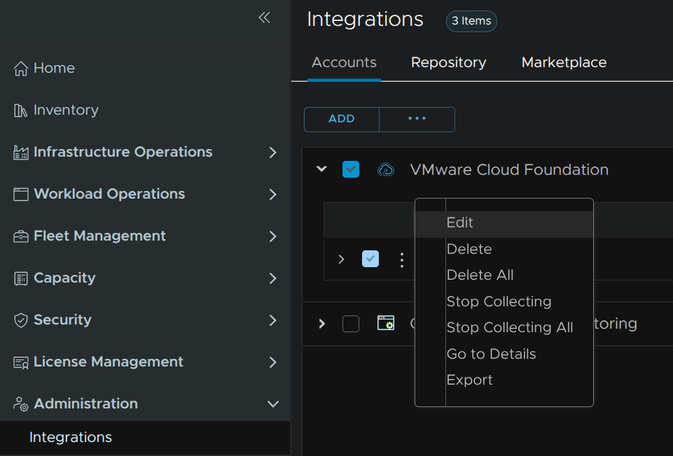
Back in VCF Operations head back to Administration/Integrations, expand the VCF integration and on your VCF instance click the three dots and click Edit
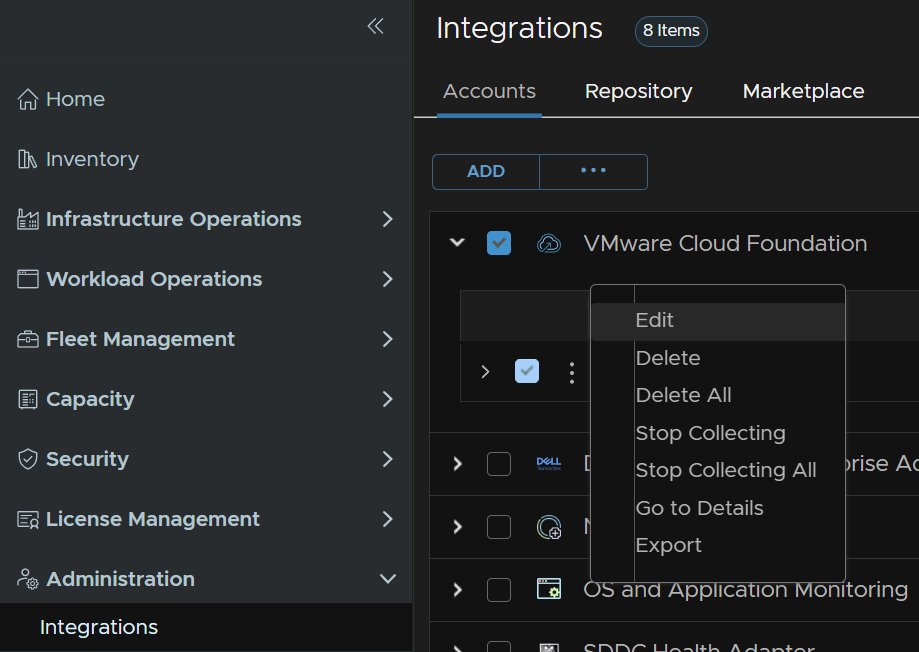
Select the domain and check the box to enable log collection, repeat for additional workload domains and click Save
5 – VCF Operations For Networks
We’ll need an FQDN registered in DNS for this and we need a root/admin password ready using the requirements from earlier
We need one for the platform appliance, with the UI and the collector
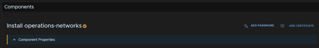
To deploy VCF Operations For Logs, in VCF Operations, head to Fleet Management/Lifecycle/VCF Management/Overview, and under operations-networks, click Add
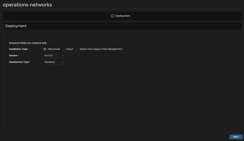
New Install should be populated on the version you downloaded, if not you’ll need to change it, then click Next
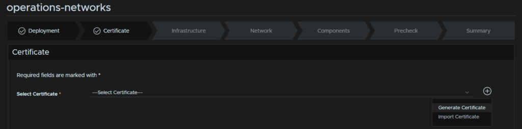
Click the + then click Generate Certificate
You can add one from a self signed CA if needed
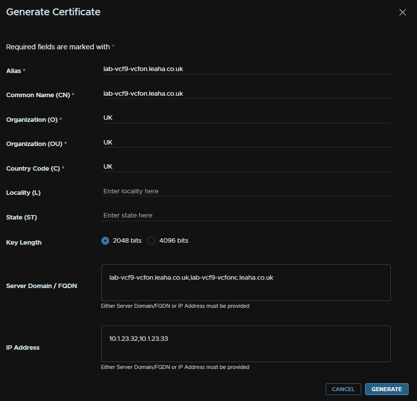
In the Alias/CN add the platform UI FQDN, O/OU/C largely dont matter for a self signed certificate
For FQDN add both the platform and collector FDQN, comma separated, and do the same in the IP Address field for the IP addresses, then click Generate
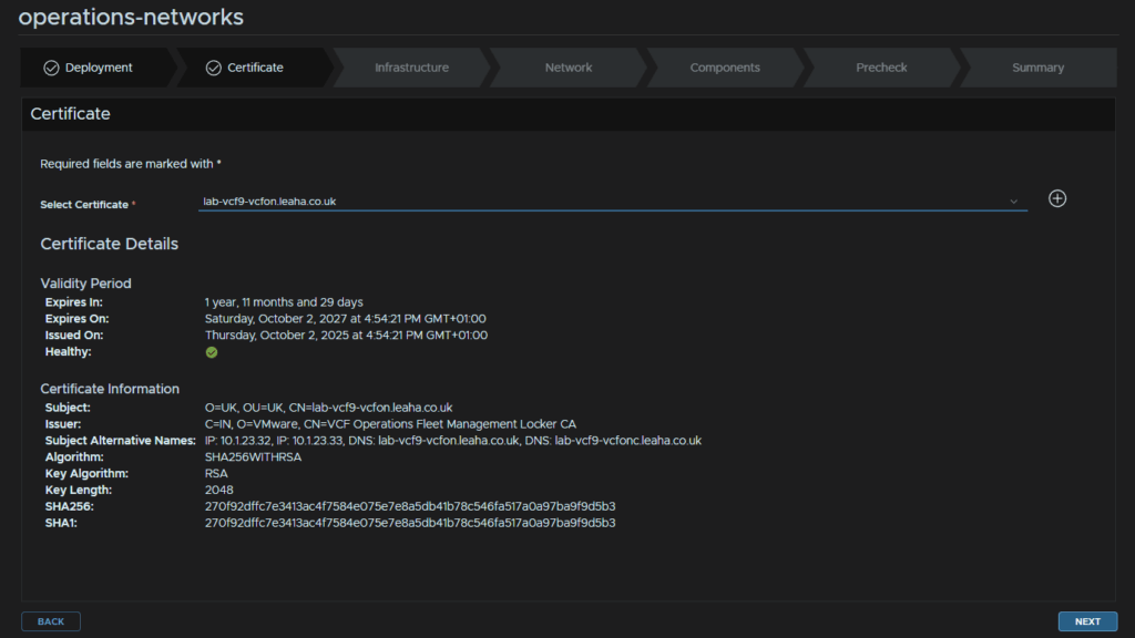
Select the certificate from the drop down and click Next
Select the vCenter and cluster, optionally, add a folder/resource pool, select the VM Management network, the one Ops is on, select the datastore and thin provisioning for the disk mode then click Next
For Network, add your domain and search domain, then click Edit Server Selection for DNS servers
Select both DNS servers and click Next
Then click Finish
For Time Sync Mode, click Use NTP Server, then click Edit Server Selection
Select the NTP server, you may have a second from the VCF Installer, then click Next
And click Finish
And enter the IPv4 gateway and subnet mask, then click Next

Click Add Password
Add an alias and enter a password meeting the requirements, this will be used for the platform/collector admin/root users, then click Add
Optionally enable FIPS if you need it, the certificate should be auto populated, then enable the Affinity Rules and select Keep VMs In Sperate Hosts, then click Select Component Password
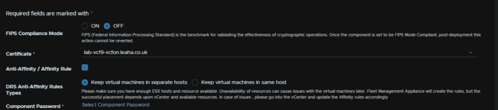
And select the password we just created
NTP should also be populated
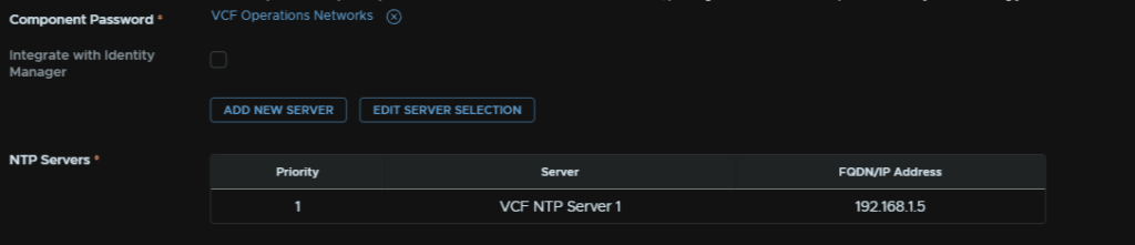
For the components, enter the VM name, IPv4 address and select a size, unless you are very large, medium will be perfectly fine, this can be scaled later if needed
Some of the networking topology features do require a larger size, but the requirements add up very quickly
Then click Next
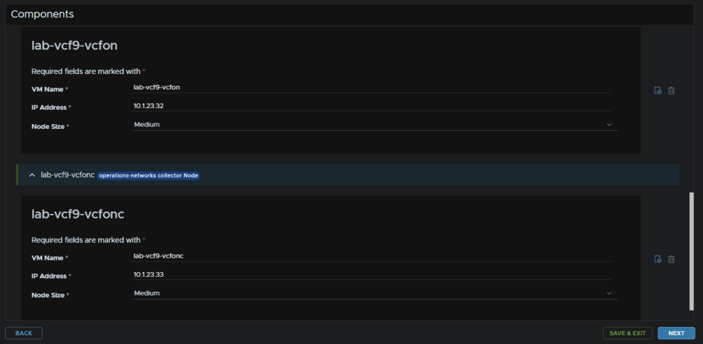
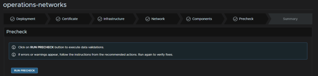
Click Run Pre Check
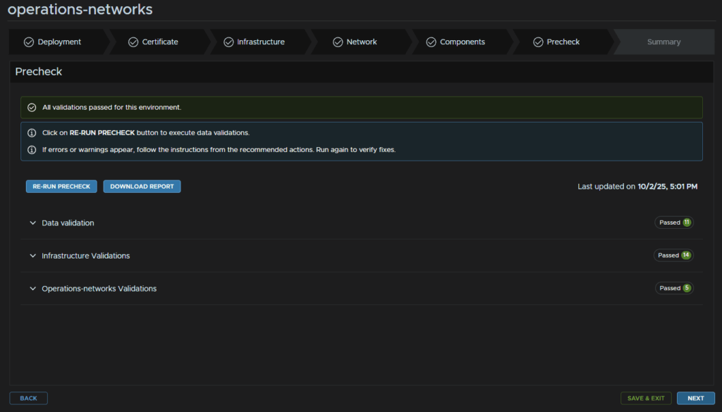
That should be all green, though any errors/warning will need to be addressed first, then click Next
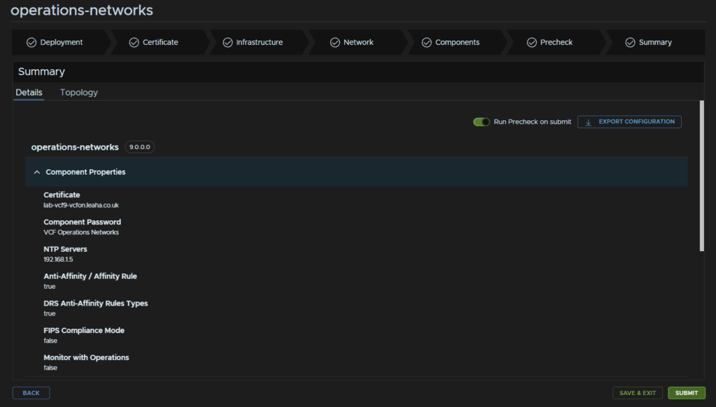
And when you are happy click Submit
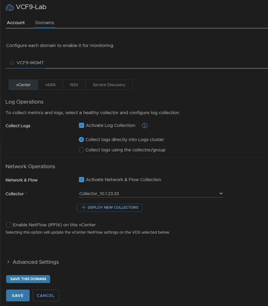
Lastly we need to enable flow collection from the VCF Integration, in VCF Ops head to Administration/Integrations, expand VCF and click the three dots on your VCF instance and click Edit
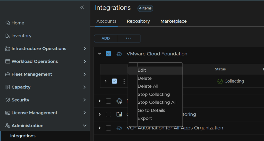
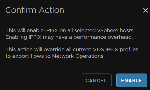
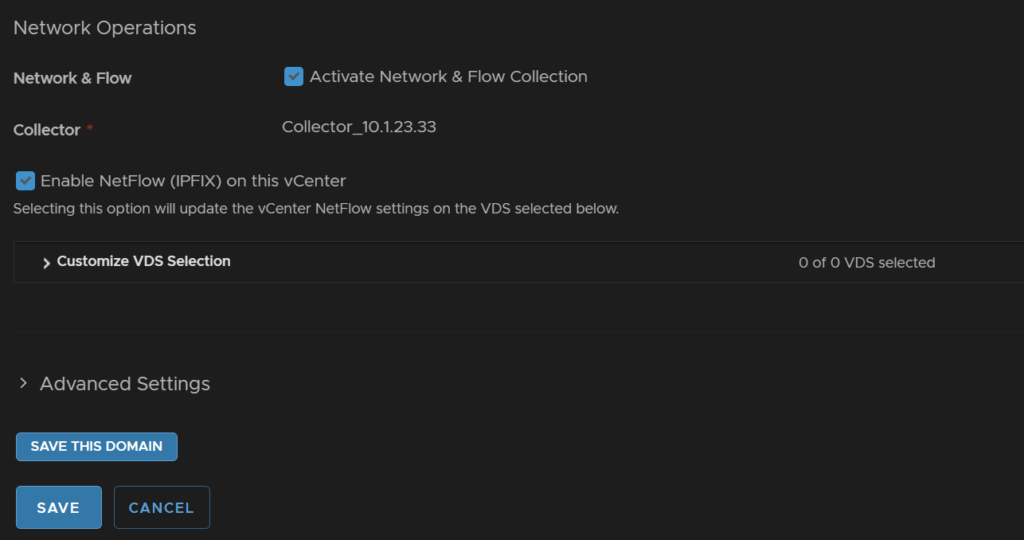
Scroll down and enable the check box for Network And Flow, select the collector from the drop down, there will only be one, and check the box to enable NetFlow
Click Enable
Then click Save
6 – NSX
6.1 – Expanding The NSX Management Cluster
The one system we really do want HA on is the NSX manager cluster, we need to expand this with the SDDC Manager API, as of 9.0.x
Thankfully we dont need to do anything complex with this, as APIs can be very confusing if you are new, Operations has an API explorer with a nice template we can use to easily do this
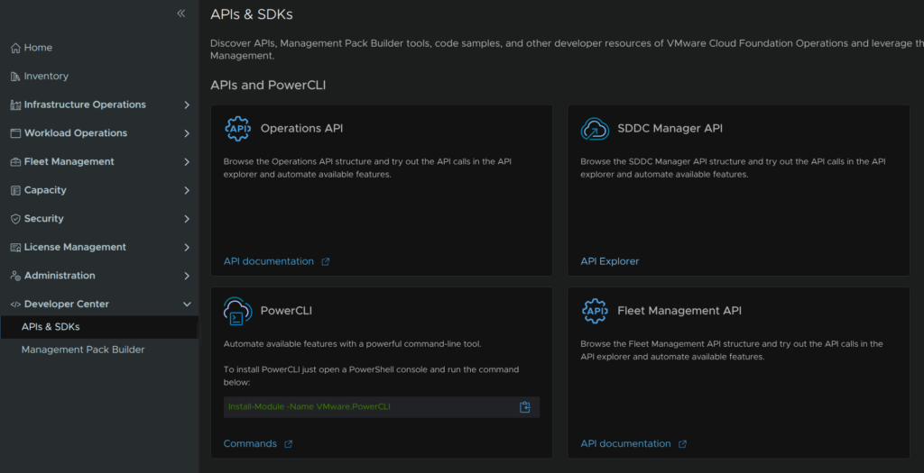
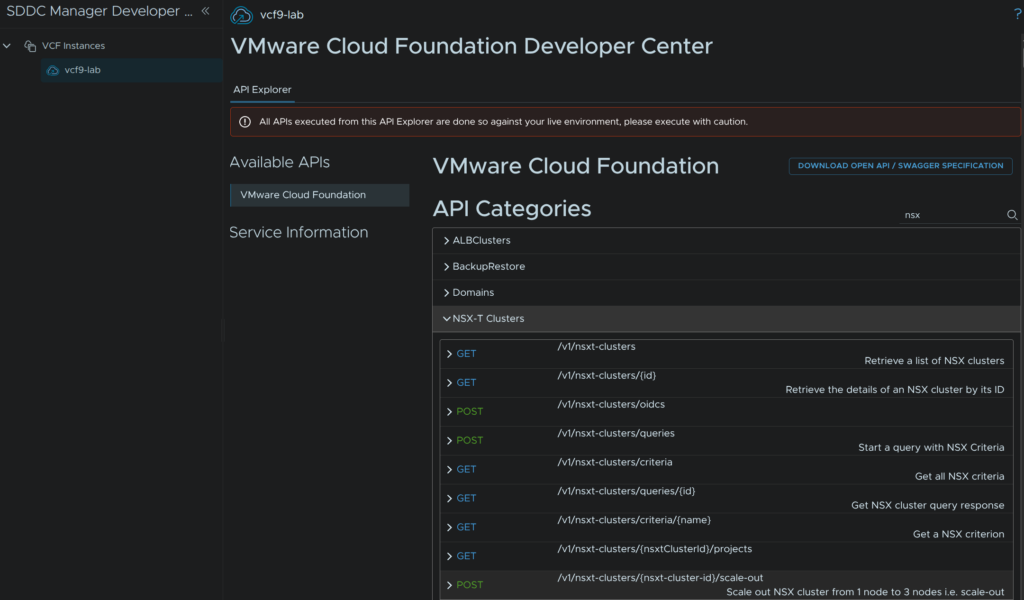
Log into VCF Operations and click Developer Center/APIs & SDKs then click API Explorer on the SDDC Manager API widget
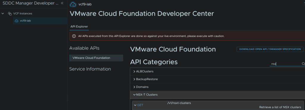
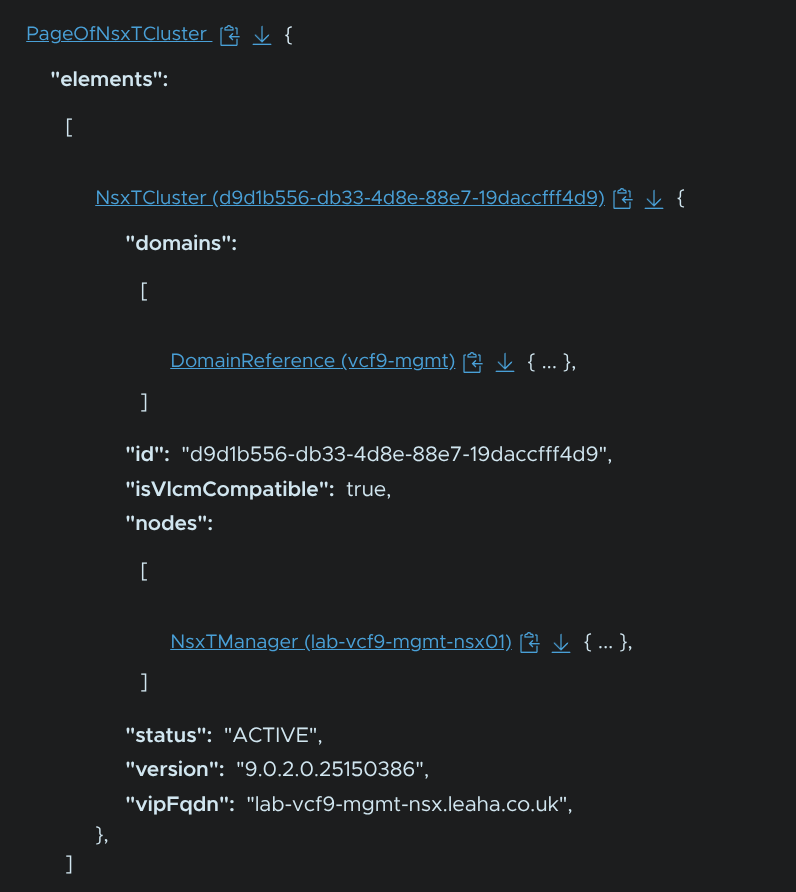
Search for NSX and the bit we want to expand is the GET request for getting our clusters, this will give us our cluster ID which we need for the scale out operation
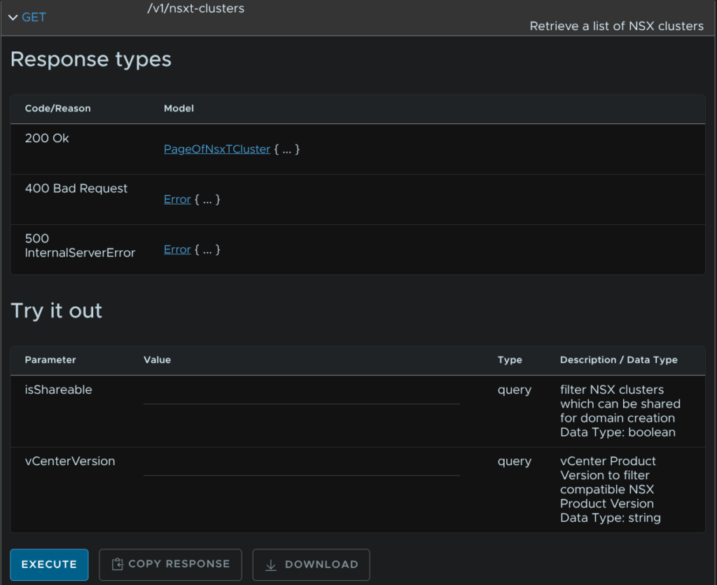
Expand the request and click Execute, you dont need to fill anything out
We can see the cluster object, you can click the link to expand it
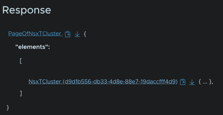
Now we can see our single node, and we have the ID we can copy for later
In my case my ID is d9d1b556-db33-4d8e-88e7-19daccfff4d9
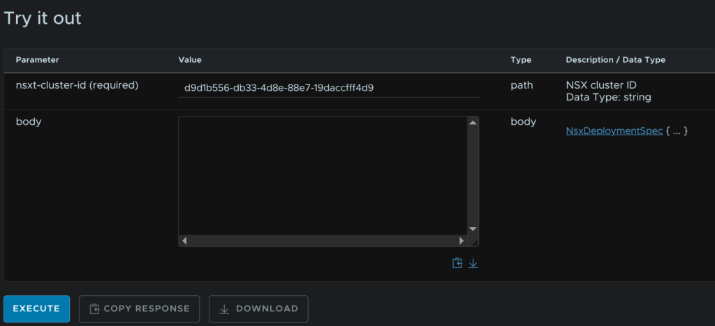
Now we need the POST request to scale out the cluster
We have two main parameters we need, the cluster ID and the body, for the cluster ID, enter your ID
We then need to add the body, the template for it is this
{
"nsxManagerSpecs": [
{
"name": "",
"networkDetailsSpec": {
"dnsName": "",
"gateway": "",
"subnetMask": ""
}
},
{
"name": "",
"networkDetailsSpec": {
"dnsName": "",
"gateway": "",
"subnetMask": ""
}
}
]
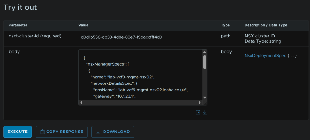
}We then need to fill our the variables like below, for each manager
- Name – Hostname
- dnsName – FQDN
- Gateway – Network Gateway
- subnetMask – Subnet mask
This is what I did for my managers
{
"nsxManagerSpecs": [
{
"name": "lab-vcf9-mgmt-nsx02",
"networkDetailsSpec": {
"dnsName": "lab-vcf9-mgmt-nsx02.leaha.co.uk",
"gateway": "10.1.23.1",
"subnetMask": "255.255.255.0"
}
},
{
"name": "lab-vcf9-mgmt-nsx03",
"networkDetailsSpec": {
"dnsName": "lab-vcf9-mgmt-nsx03.leaha.co.uk",
"gateway": "10.1.23.1",
"subnetMask": "255.255.255.0"
}
}
]
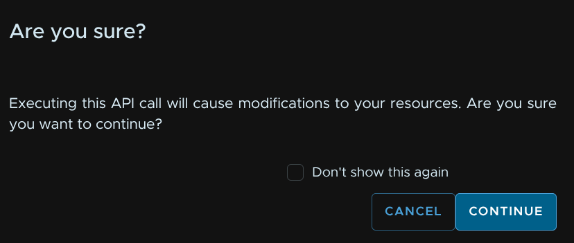
}Then click Execute
Its worth noting this will execute the command on your environment, if you are happy, click Continue
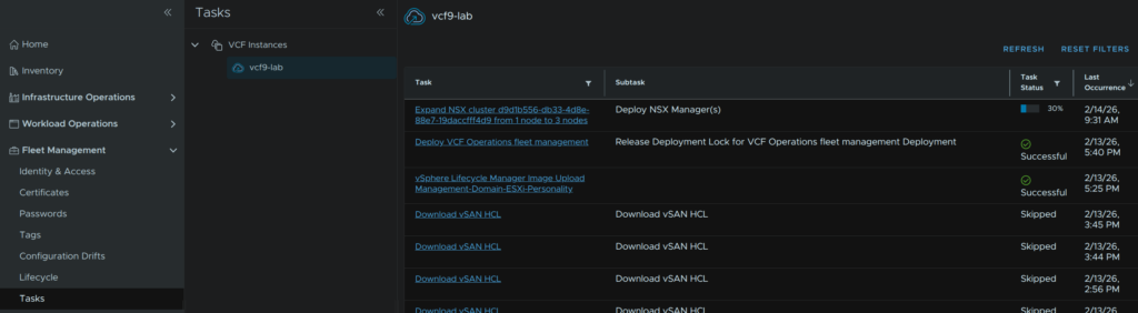
We can view the status from Fleet Management/Tasks and then select our VCF instance
6.2 – Setting Up NSX Networking
Now we have the extra appliances deployed we need some Edge VMs to do the network transport
We need two DNS registered FQDNs for this
Its here that we need our Uplink VLANs for BGP
I would recommend having ToR 1 owning Uplink 1 as the BGP neighbor on this subnet, and ToR 2 owning Uplink 2
In my lab, I only have 1 OPNsense router, so it my case it will own both Uplink VLANs
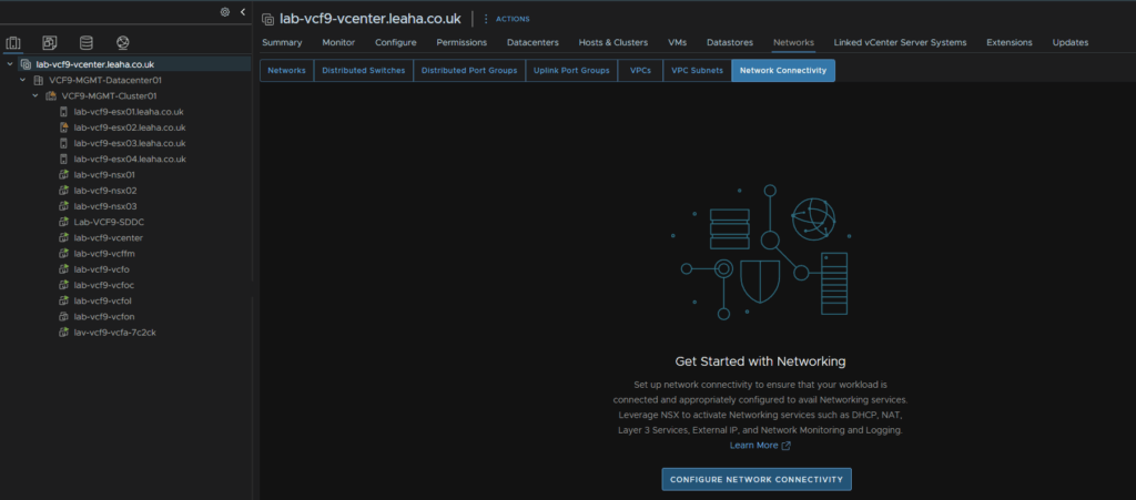
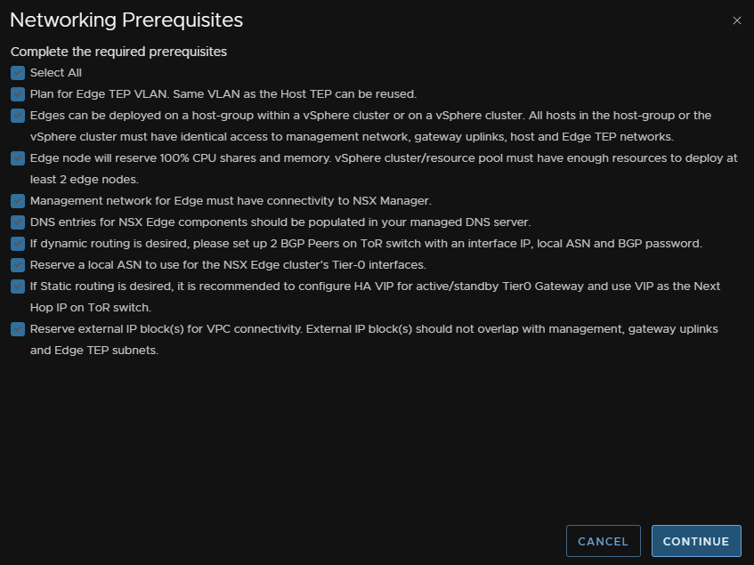
In vCenter, click the vCenter its self then Networks/Network Connectivity and click Configure Network Connectivity
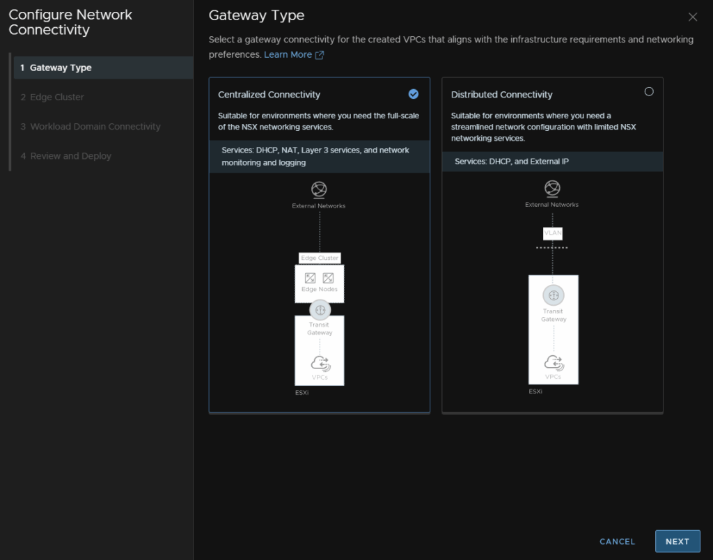
Select Centralized Connectivity and click Next
Check the Select All Box, reviewing the prerequisites, and click Continue
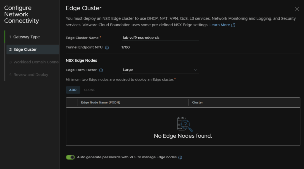
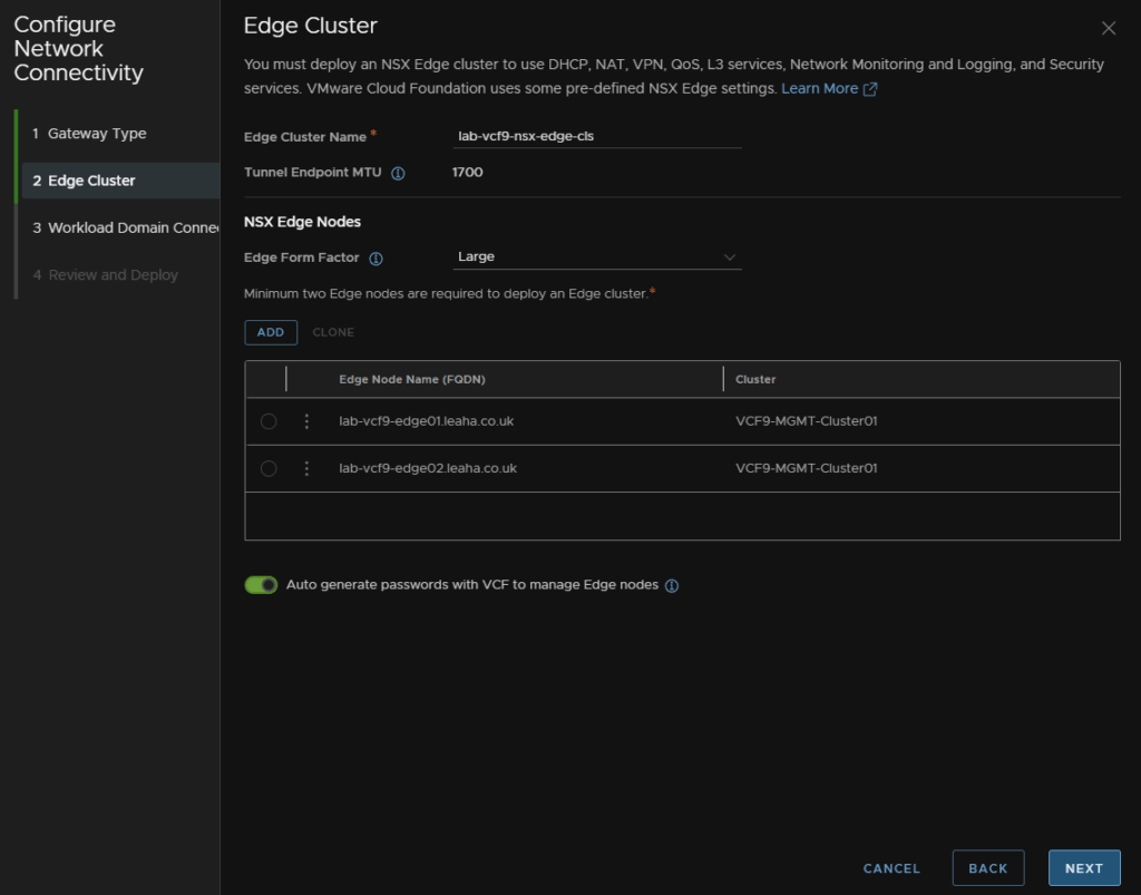
Give the Edge cluster a name, select the Large form factor and click Add
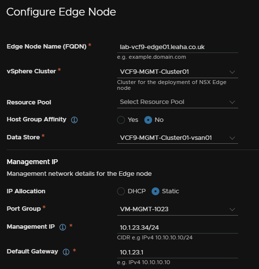
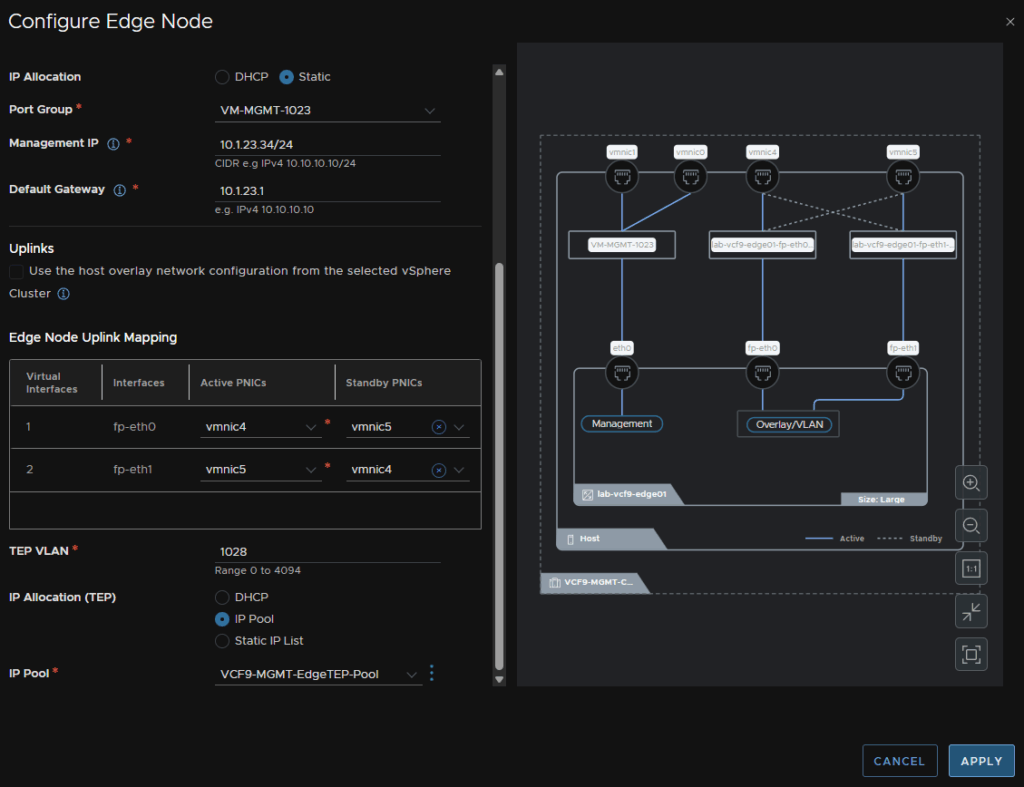
Enter the node FQDN, select the cluster, optionally add a resource pool, leave host affinity on No, select a datastore
Then for the management IP select Static, then add the VM Management port group, enter the management IP in CIDR address and add the gateway
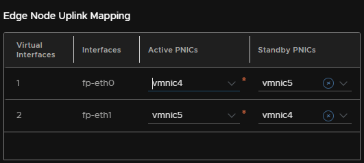
For the Active PNIC, select the first uplink on the VDS used for NSX traffic
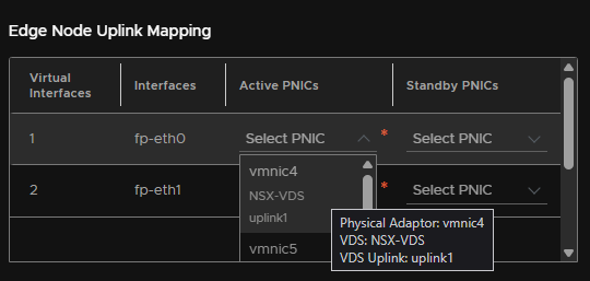
This will correctly auto populate the rest
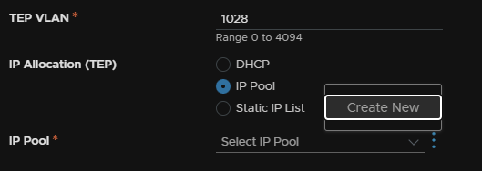
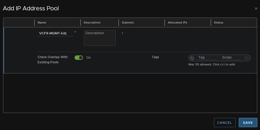
Enter the Edge TEP VLAN, select IP pool, then click the three dots and click Create New
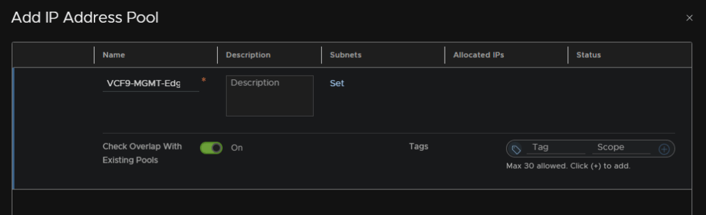
Give it a name and click Set under Subnets
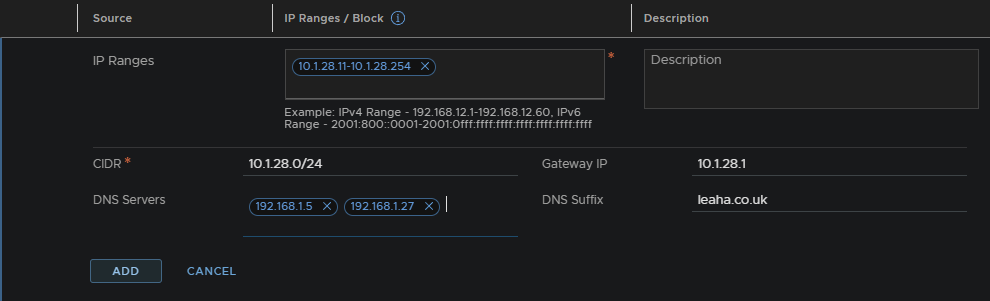
Click Add Subnet/IP Ranges
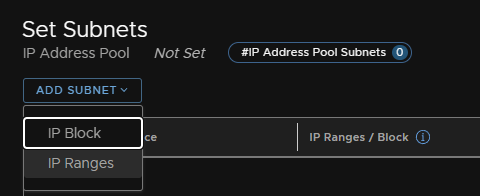
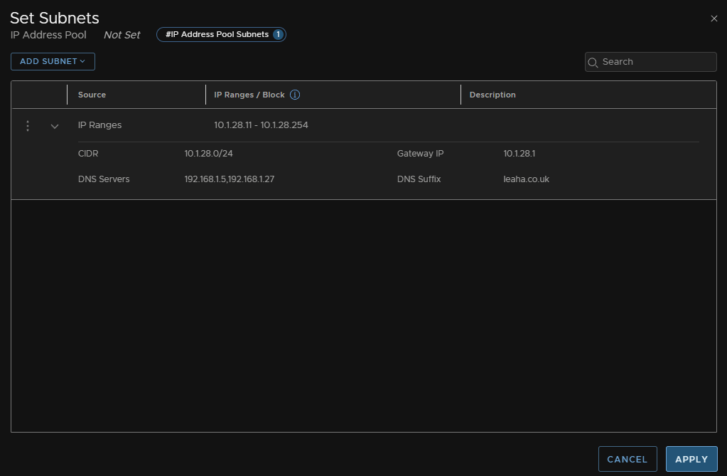
Add an IP range for TEPs, as the whole VLAN is dedicated for this I used almost all the IPs, then add the network in CIDR notification, gateway, DNS servers and DNS suffix then click Add
Then click Apply
And click Save
Then click Apply
And repeat for the second Edge Node
Once thats done it should look like this, then Click Next
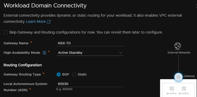
We then need a name for the, enter a name for the T0 gateway, keep HA on Active/Standby, this is very difficult to change later, and Active/Active isnt supported for the supervisor with VPC, routing needs to be BGP, and we then need a local AS number, this must be unique on your network
My lab router has ASN 65535 and thats all I have
But you might want something like ToR1 on 65534 and ToR2 on 65535
I used 65530 for the edge cluster
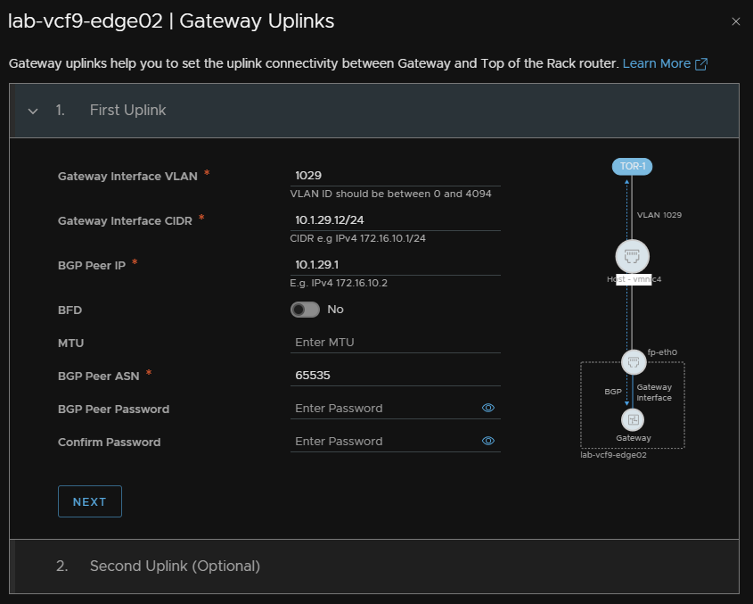
For gateway uplinks click Set
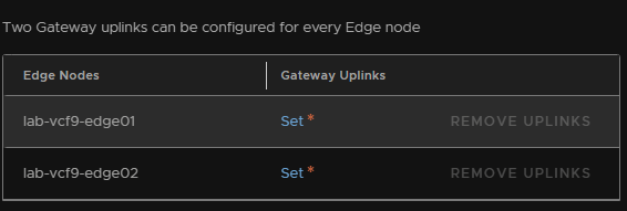
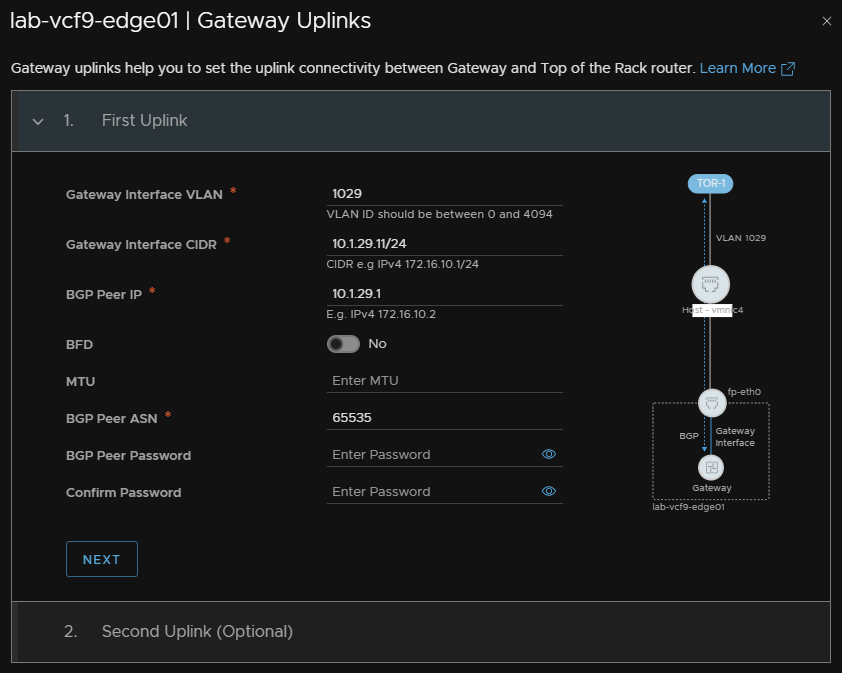
Now we need to enter the details for the Uplink 1 VLAN
Enter the VLAN ID, interface CIDR, this is the UP the Edge will have and much be unique, gateway IP the ToR has, and enter the ASN number configured on ToR1, then click Next
Repeat for Uplink 2 and click Apply
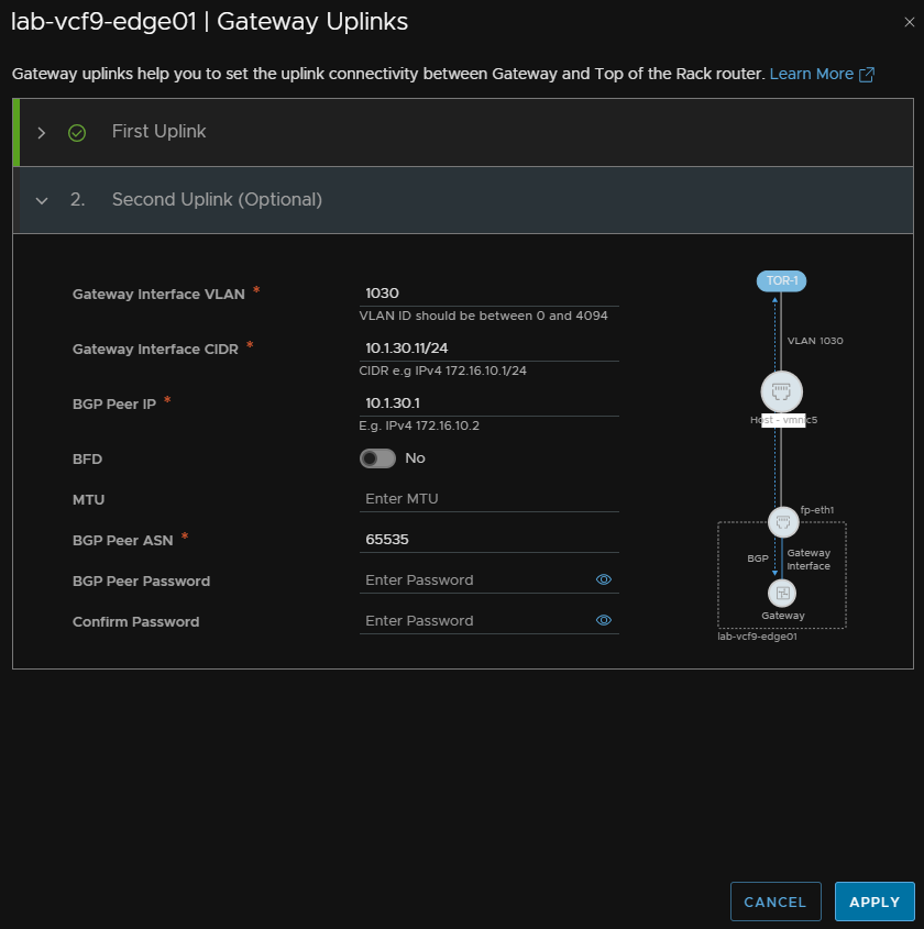
The same config should be applied to the other Edge node
Uplink 1
Uplink 2
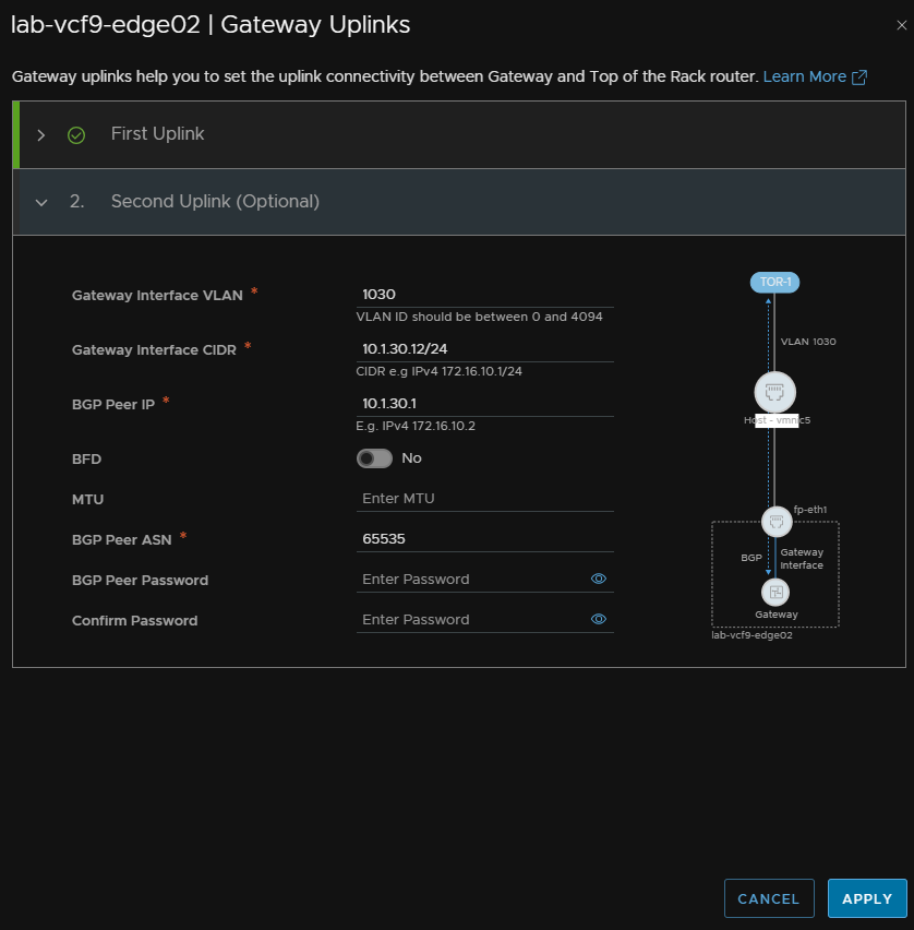
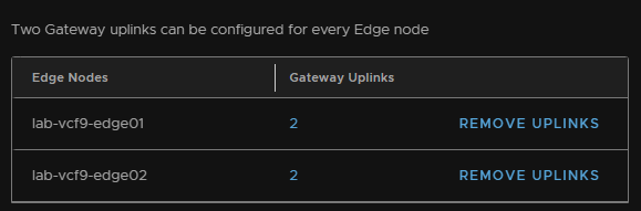
When its done it should look like this
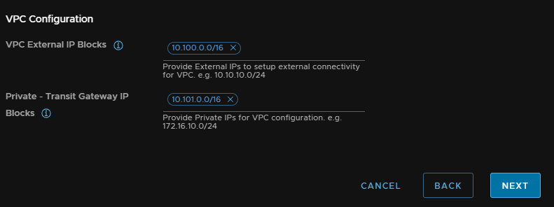
We then need our VPC connectivity, we need two large subnets, I recommend /16s, that can be split out as needed within VPCs, these blocks should not overlap anywhere else on your network
I opted for 10.100.0.0/16 and 10.101.0.0/16
Then click Next
Review the config and when you are happy, click Deploy
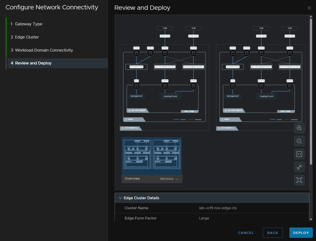
You will need to update your BGP config on the ToRs with the addresses the Edges have on each uplink VLAN so BGP is then communicating properly
7 – Supervisor/VKS
7.1 – Deploying The Supervisor
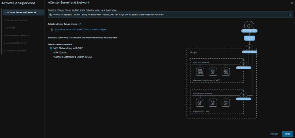
To get access to K8S in vSphere, or the new All Apps organisation type in VCF Automation, we need the supervisor deploying
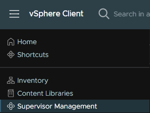
Ib vSphere, click the three lines in the top left and click Supervisor Management
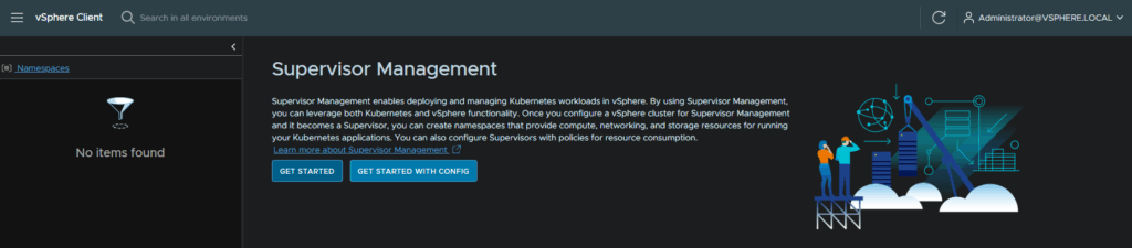
Then click Get Started
Make sure you have selected VCF Networking With VPC and click Next
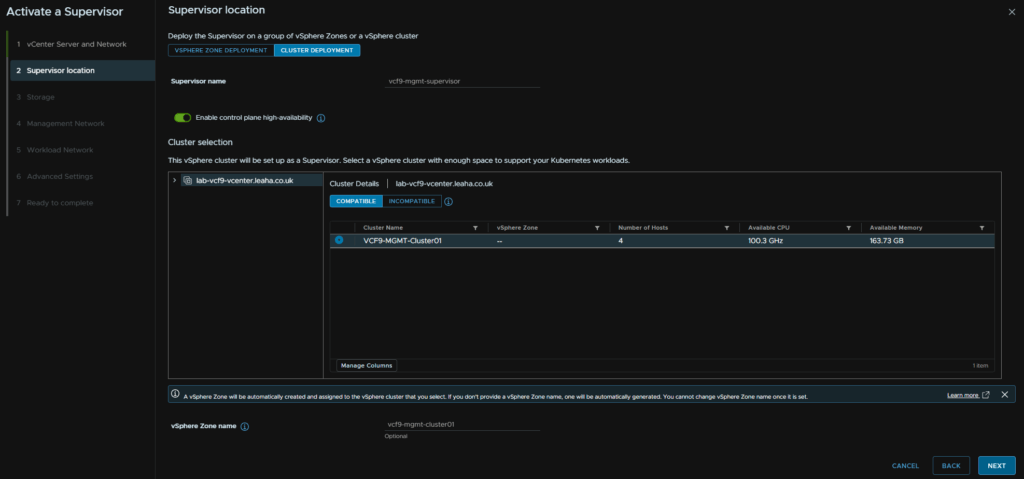
Click the Cluster Deployment tab, then enter a name for the supervisor, make sure the toggle is selected for control plane HA, select the cluster, and optionally provide a zone name, I recommend the cluster name, it must be all lower case, if you dont enter one, the system will generate one and it cannot be changed
Then click Next
Select a control plane storage policy, I recommend the vSAN default for a 4 node or less, or you can use the ESA default, likely RAID 5 on a 5 node cluster or larger, then click Next
If you are using VMFS you will need to create your own and this must be a thick provisioning policy, thin can be used for deployments within namespaces however
Then click Next

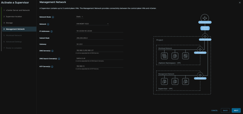
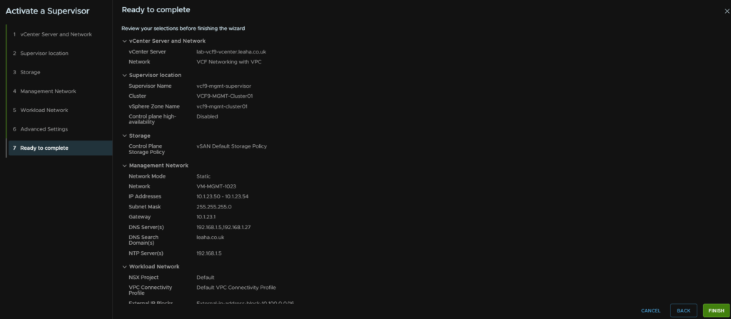
For the control plane networking, set the mode to static, then select the VM Management port group all our VMs like VCF Ops and vCenter are on, then enter a block of 5 IPs, add the subnet mask, gateway and DNS search domain, DNS/NTP should be pre populated, if not add them, comma separated, then click Next
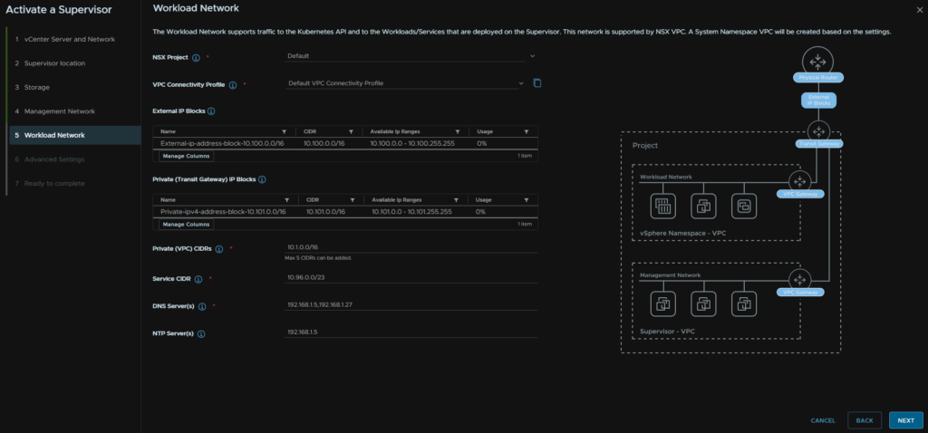
The NSX project and VPC connectivity profile should be automatically populated with the External and Private Transit gateway IP blocks
We then need private VPC blocks for the workload, this can overlap with any other network, I recommend a /16, I used 10.1.0.0/16, the service CIDR can be left at the default, then add your DNS/NTP servers, comma separated and click Next
For the control plane size, small should be fine for most environments, we can add a DNS registered FQDN for accessing the API, we will need at a later point during the Supervisor configuration guide, for now ensure this isnt bound to any FQDN, then click Next
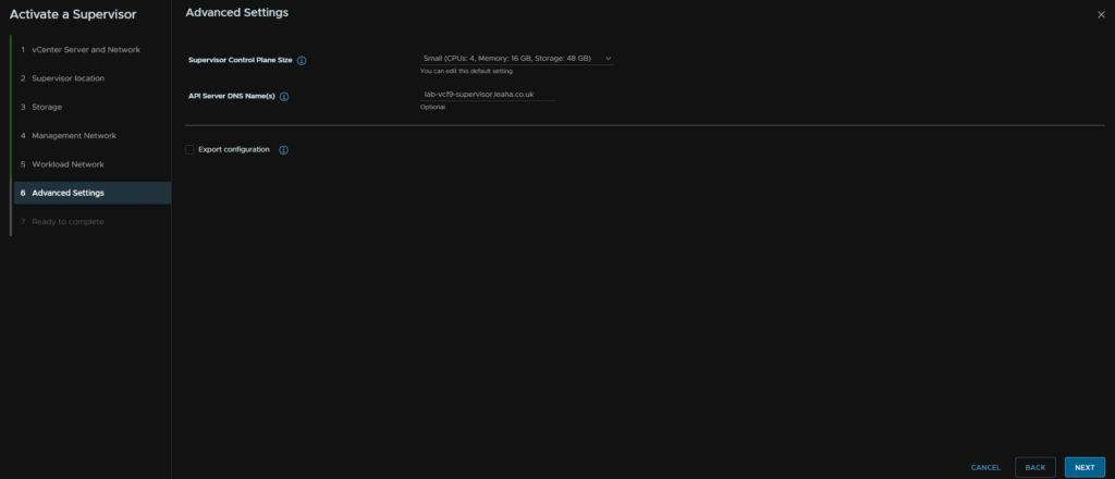
Then review and when you are happy click Finish
7.2 – Deploying The Consumption interface
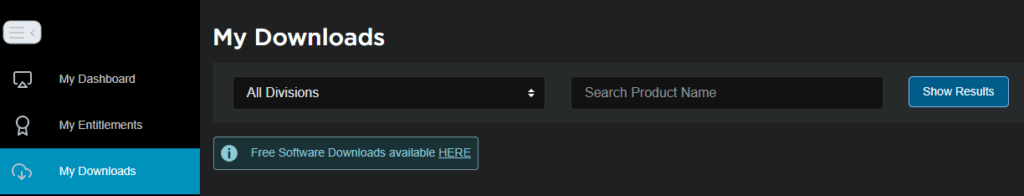
First, we need to get the service files from the Broadcom portal, head to My Downloads and click the HERE button for Free Software Downloads
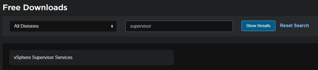
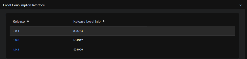
Search and click vSphere Supervisor Services
Expand Local Consumption Interface and click on the latest release, eg 9.0.1
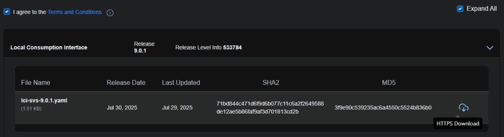
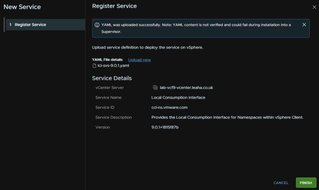
Click the Terms And Conditions like to enable the check box, then click the download icon on the right for the YAML file
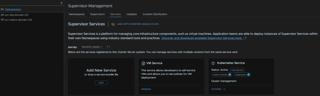
In vSphere click the three lines in the top left and click Supervisor Management

Then click Services and on the Add New Service widget, click Add
Then click Add
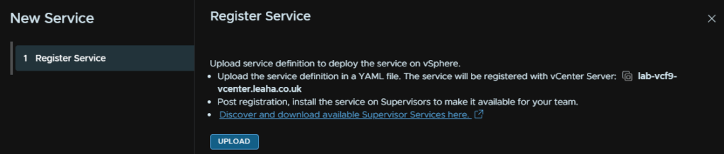
Double click the YAML file

Then click Finish
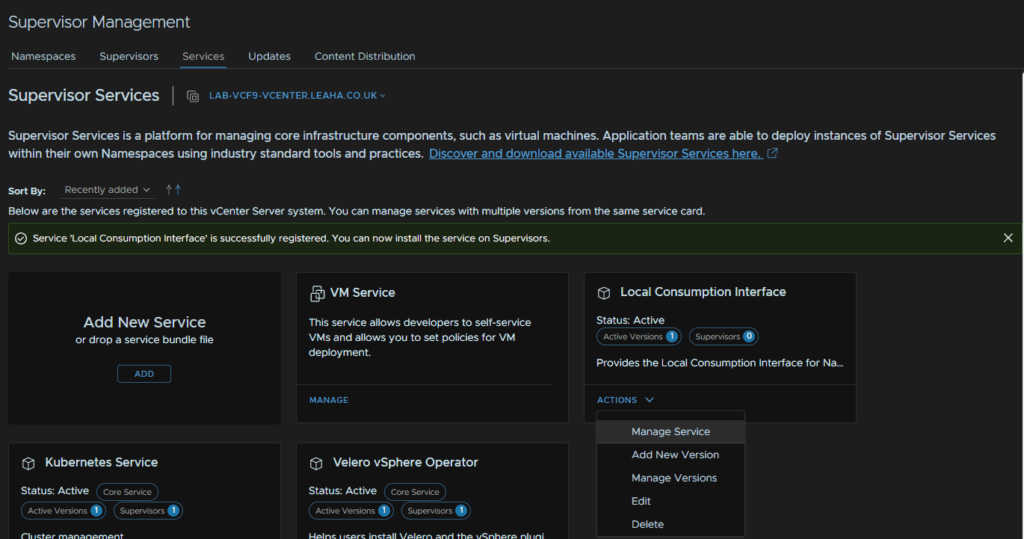
We can then click on the Local Consumption Interface Widget and click Actions/Manage Service
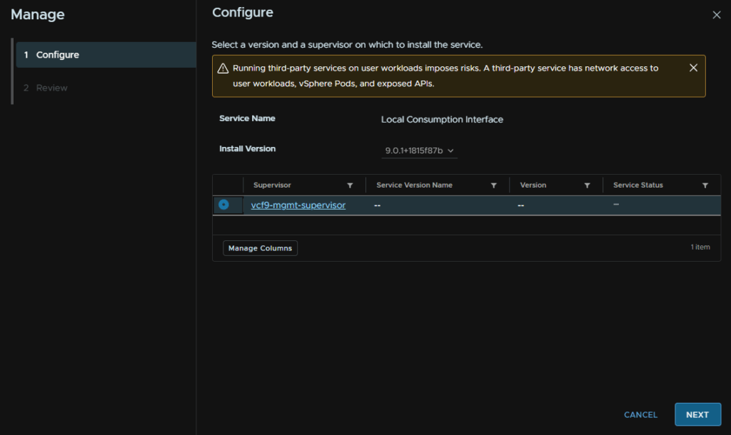
Select our supervisor and click Next
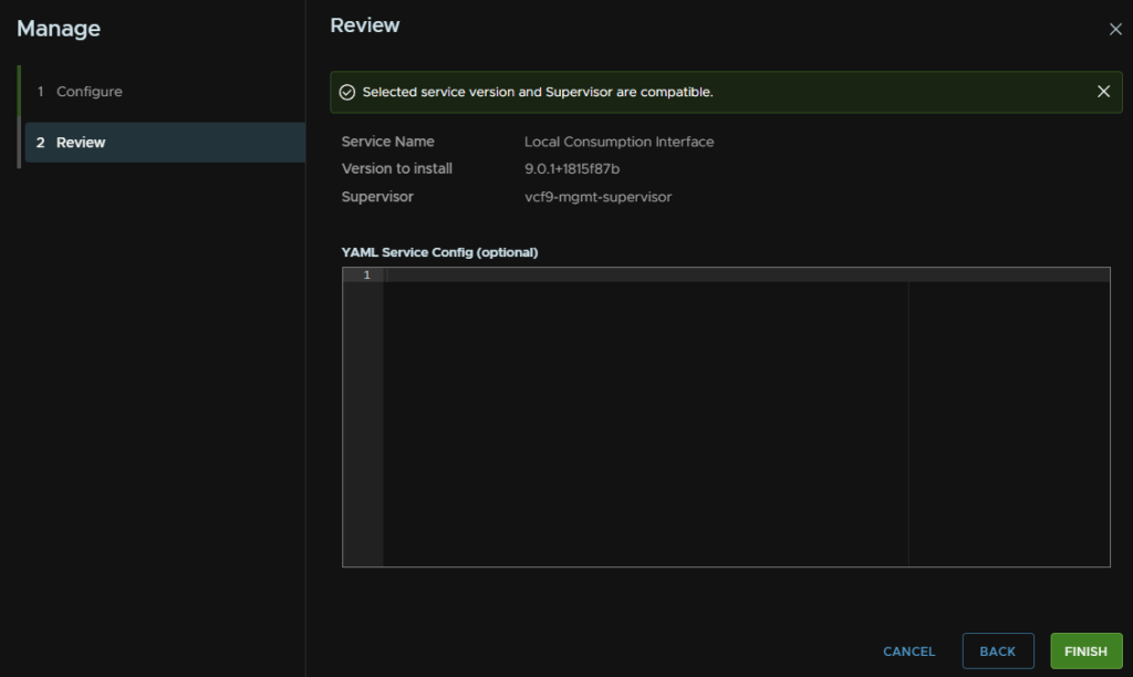
Wait for the pre check to run and click Finish
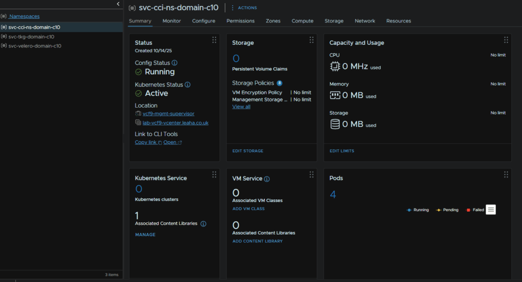
This will generate a new namespace and we can wait for the pods to deploy
8 – Post Deployment Steps
8.1 – vCLS Retreat Mode
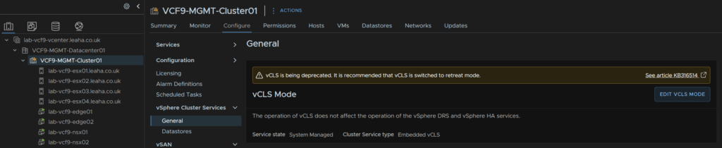
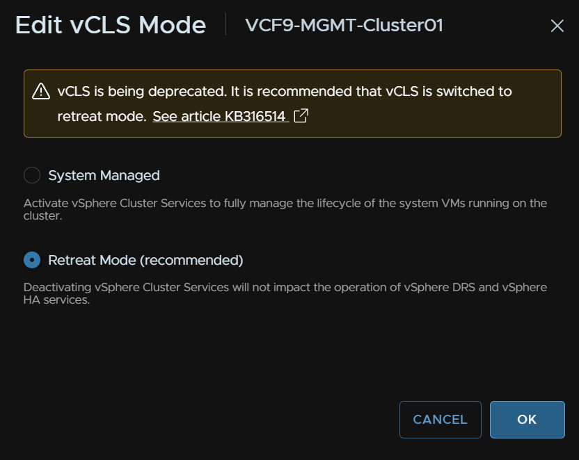
VCF 9 doesnt need vCLS services and it will be removed in the future, to put it into retreat mode, click the cluster and head to Configure/vSphere Cluster Services/general and click Edit vCLS Mode on the right
Select Retreat Mode and click Next
8.2 – Remove NSX Password Expiry
The NSX passwords will expire after 90 days, and with SDDC managing them, and there being a total of 7 appliances, with three accounts each, password expiry is going to be a problem, give we have random 15+ character passwords, I would suggest disabling password expiring for the NSX appliances, but this is entirely optional
Sadly, SSH is disabled, so this will have to manually done via the console, when you are logged in run
set user admin password-expiration 9999
set user audit password-expiration 9999
set user root password-expiration 9999
You can confirm this with
get user admin password-expiration
8.3 – Licensing
I ran out of VCF 9 licenses in the portal so I couldnt license this lab, so the below steps are from another environment so hostname will be different but the steps are identical
Licensing is no longer handled by Keys in vCenter, rather through VCF Ops and the Broadcom Business Services
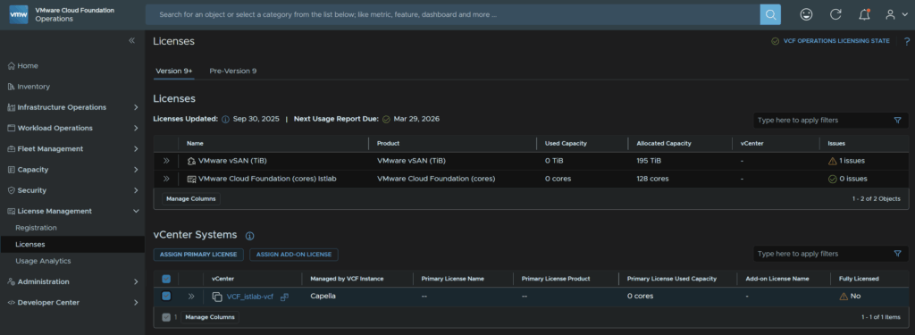
If you have an active subscription then youre licenses should show up here
Under License Management/Licenses
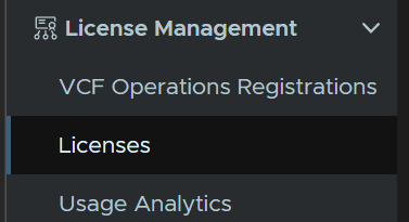
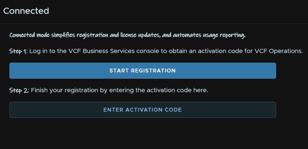
To set this up click License Management/Registration
Now we will assume you have internet connectivity and will do a connected registration, on the Connected Widget, click Start Registration
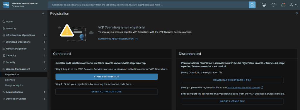
This will prompt you to log into the Broadcom portal, you will need licensing permissions in your Broadcom portal for your organisation
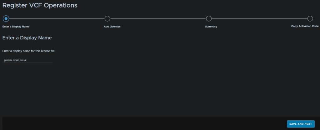
On the default loaded page, enter a display name for the license and click Save And Next in the bottom right
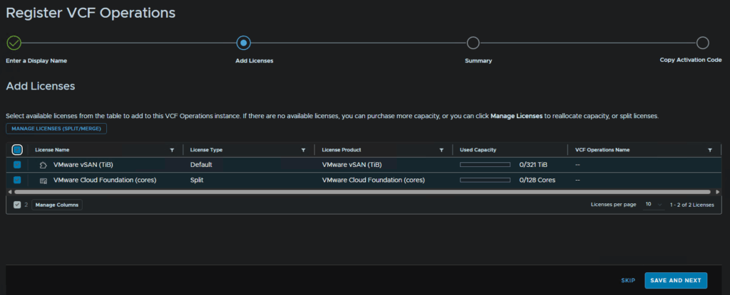
Select your license, I am selecting my VCF license and vSAN, then click Save And Next
Then click Next
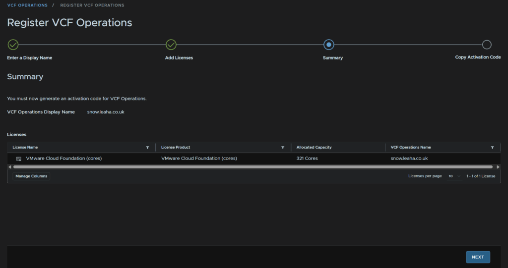
Click Copy next to the activation code
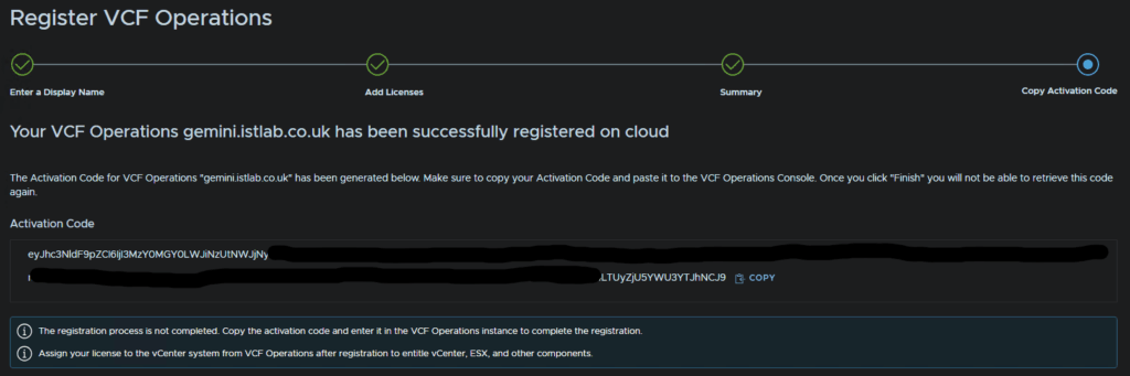
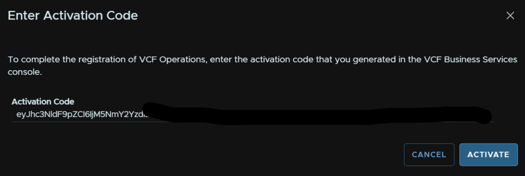
In VCF Ops click Enter Activation Code
Then click Activate
Now we can head to License Management/Licenses, click our vCenter in VCF Ops, mine is called VCF_istlab-vcf and click Assign Primary License
If yours doesnt show up here, check out the bottom in section 1.12 and changing the SDDC manager integration as this will be needed
Select our license and click Assign
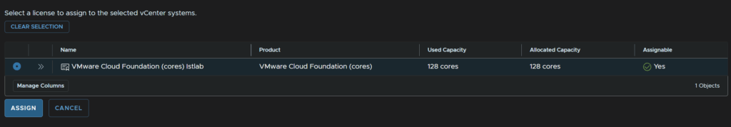
Wait for it to be applied

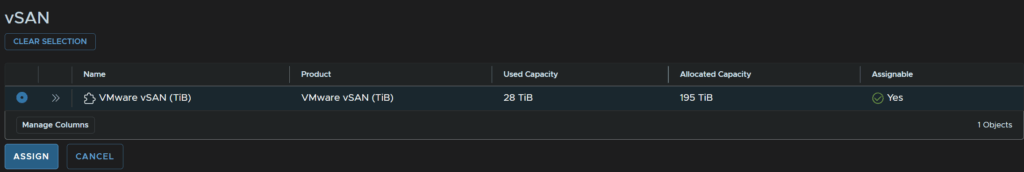
We need to also click Assign Add On License for vSAN
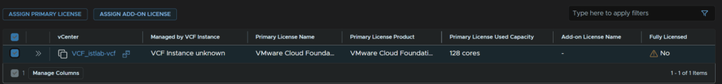
Select the vSAN license and click Assign
We can then see our cluster is fully licensed and we can see the usage
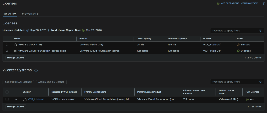
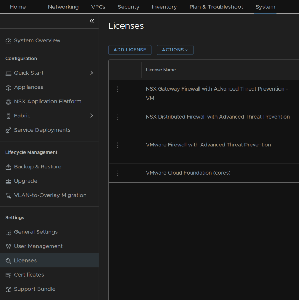
Its worth noting the vDefend licenses arent here and need to be applied directly to NSX, you can get the keys from your entitlements like with VCF 5.2 licenses
Then in NSX, from System/Settings/Licenses, we can click Add License and copy the keys over
8.4 – Backups
The best practices method to backup a vCenter is to use the config backups in VAMI
To access VAMI go to the following link substituting fqdn for your vCenters FQDN
https://fqdn:5480
You can log in here with the local root account, or an SSO admin login
Now head to the backups tab at the bottom on the left, from here you can click ‘Configure’ on the right to setup a schedule
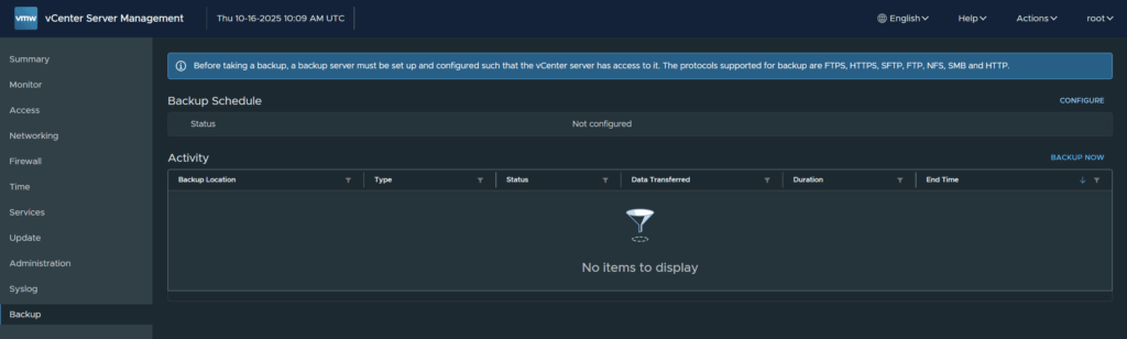
You’ll need a valid backup location to store them, an SMB, NFS or FTP server work best but you can also use HTTPS and FTPS
The backup schedule will give you a format for the backup location

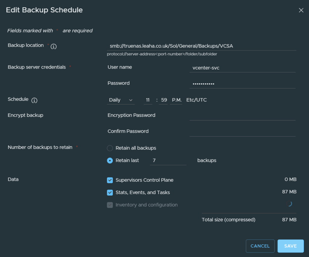
We want to setup our location, here I am using an SMB server, but for NFS/SFTP the process is the same you just change the protocol at the start to NFS or SFTP respectively
We can also add in an account with read/write permissions to the share, I recommend a service account with a password that wont expire, as if it expires and you forget, the backups will stop working
You can encrypt the backup, however you must not loose the password else you cant restore it
You’ll want it to run daily, ideally if you need to restore you dont want a backup older than 24 hours
Retain the last 7 backups, this will remove older backups and maintain its self
And check all boxes at the bottom to back up everything
Then hit create
To test this works, run a manual backup by clicking backup now on the right

Click use backup location and username at the top of the pop up, this will pull the settings from the schedule, you’ll just need to enter the account password
Then click start
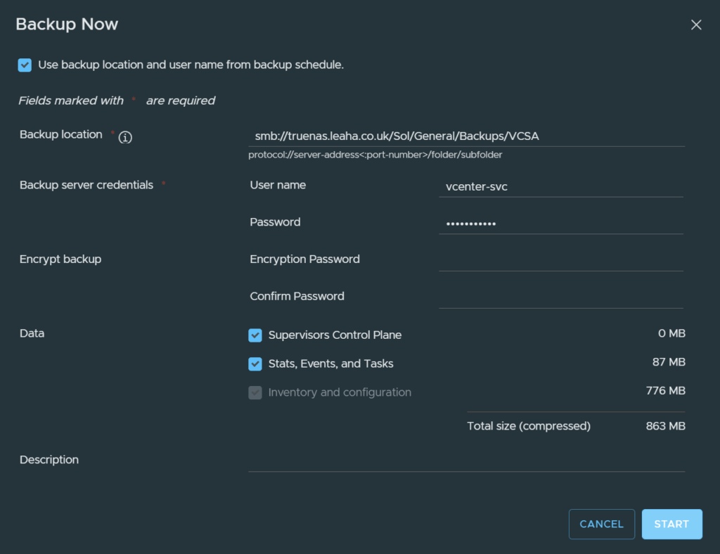
That will create a manual backup task

If all is working, this should complete with no errors

Now your vCenter is backed up and will automatically back its self up everyday for you, so if something goes wrong you have a way to restore it
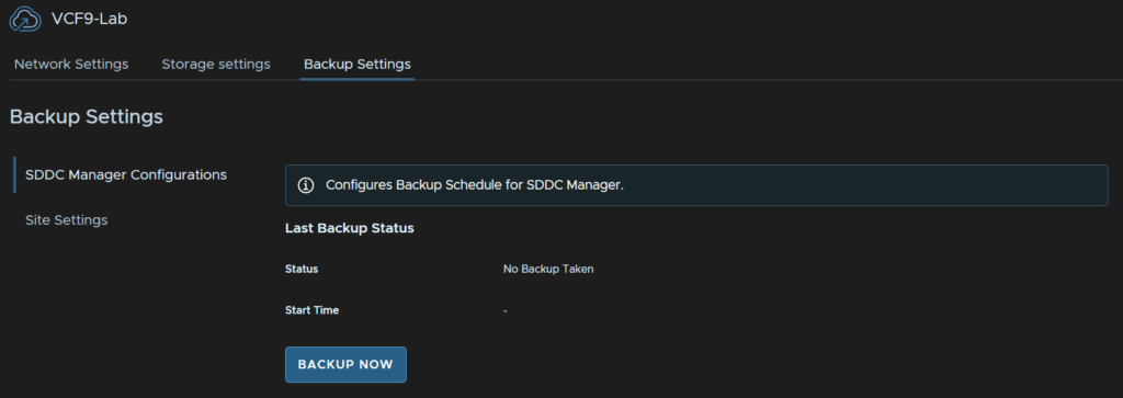
We then need to configure the SDDC Manager backups, in VCF Operations, click Administration/SDDC Manager and click your VCF Instance
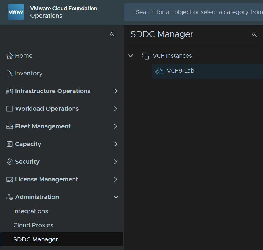
Click Backup Settings/Site Settings
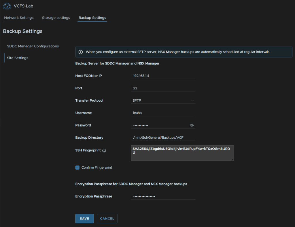
Then enter your SFTP server fqdn, the port will be 22, protocol is SFTP, there are no other options, enter the username/password for the SFTP server, I recommend a service account
Then add the backup directory for where you want to store the backups, click Confirm Fingerprint, enter a passphrase for the backups and click Save
The passphrase should be 15 characters, the only allowed special characters are !@#$%^&*
Mine did also error on the FQDN which was odd, you can just enter the IP instead which solved that
Then click Confirm
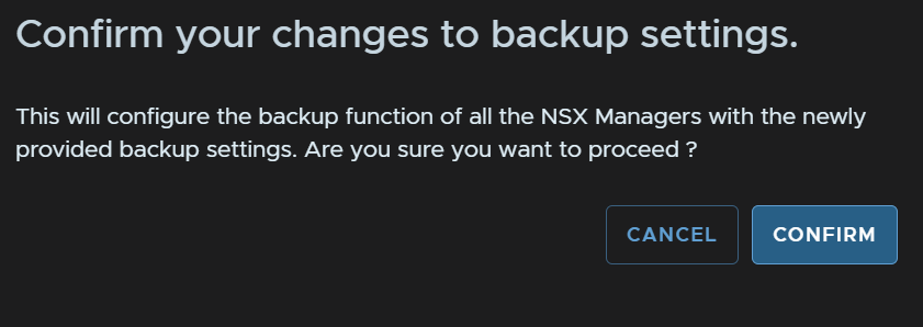
We need to wait for this configuration to complete
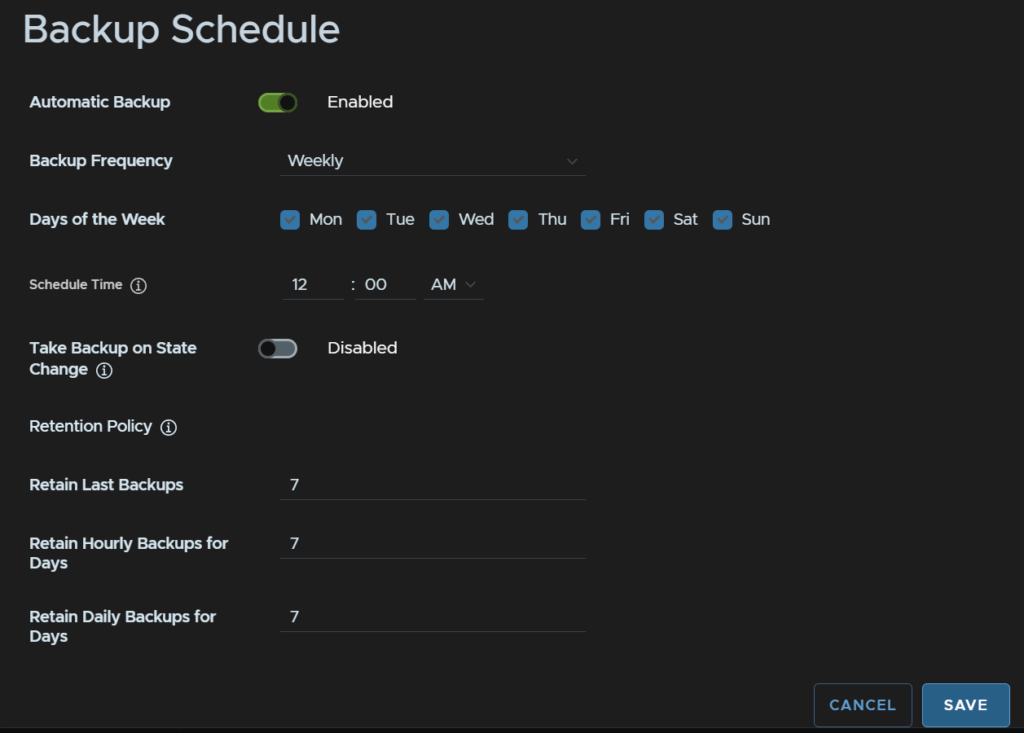
Then click SDDC Manager Configurations and click Edit under Backup Schedule

Click the toggle to enable the schedule, set the frequency to weekly and select all days, for daily backups, add a time, you can optionally do backups on a state change, then set the retention policy, which I need 7 days, then click Save
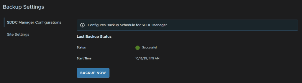
Then click Backup Now to make sure it works
And make sure its successful
Lastly we need some backups for the fleet management servers, click Fleet Management/Lifecycle/VCF Management
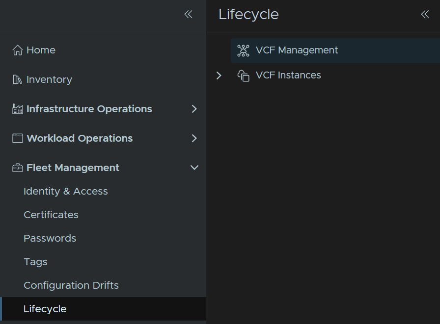
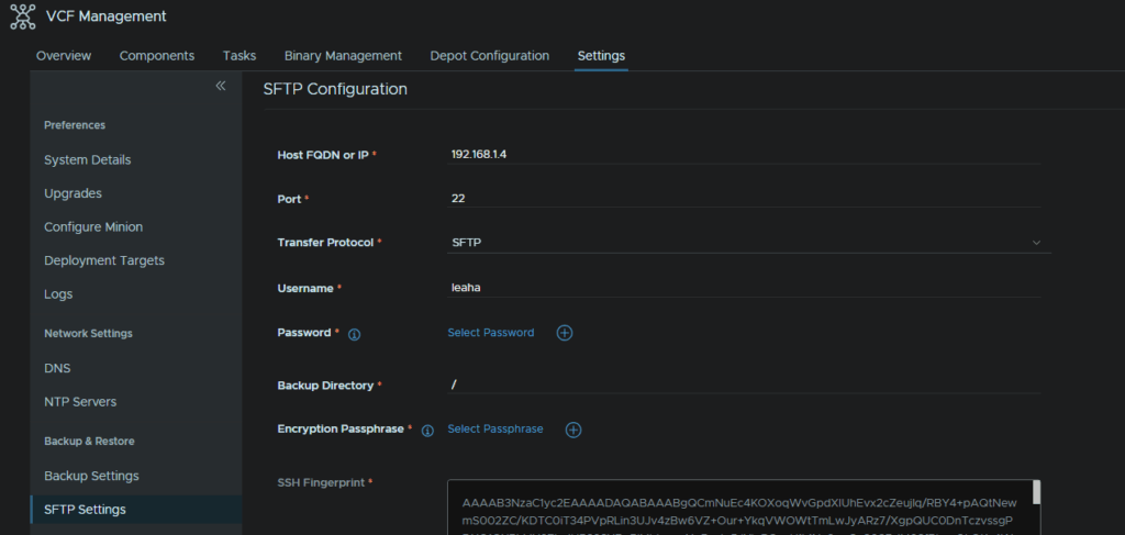
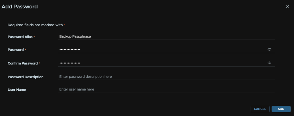
Click Settings/SFTP Settings, then add your backup server IP, I tried the FQDN but got resolution issues on internal K8S pods so I recommend using the IP, port 22, SFTP protocol, username, I recommend a service account, and click the + to add a password
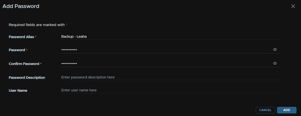
Add an alias, a friendly name, then the password and click Add
Click Select Password

And select the password

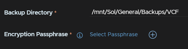
Enter the directory to save the backups on the SFTP server, then click the + for a passphrase
Enter an alias, the password, and click Add
The passphrase should be 15 characters, the only allowed special characters are !@#$%^&*
Then click Select Passphrase

And select the password

Then click Fetch Fingerprint
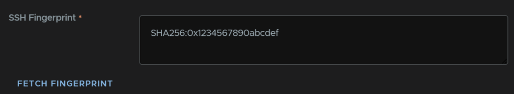
And click Save
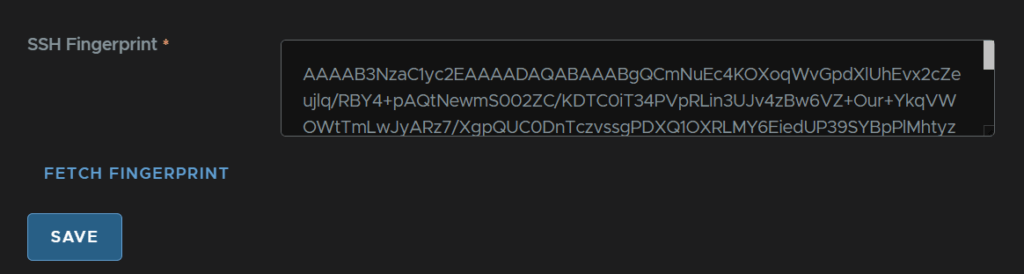
This will trigger an SFTP server update

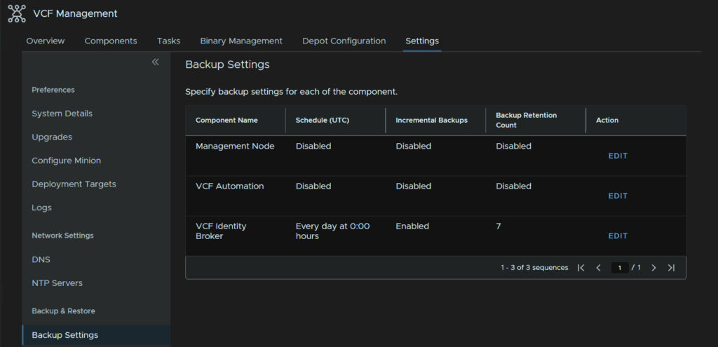
We can then configure a schedule for the automation appliance
In Settings/Backup Settings click Edit on the Management Node
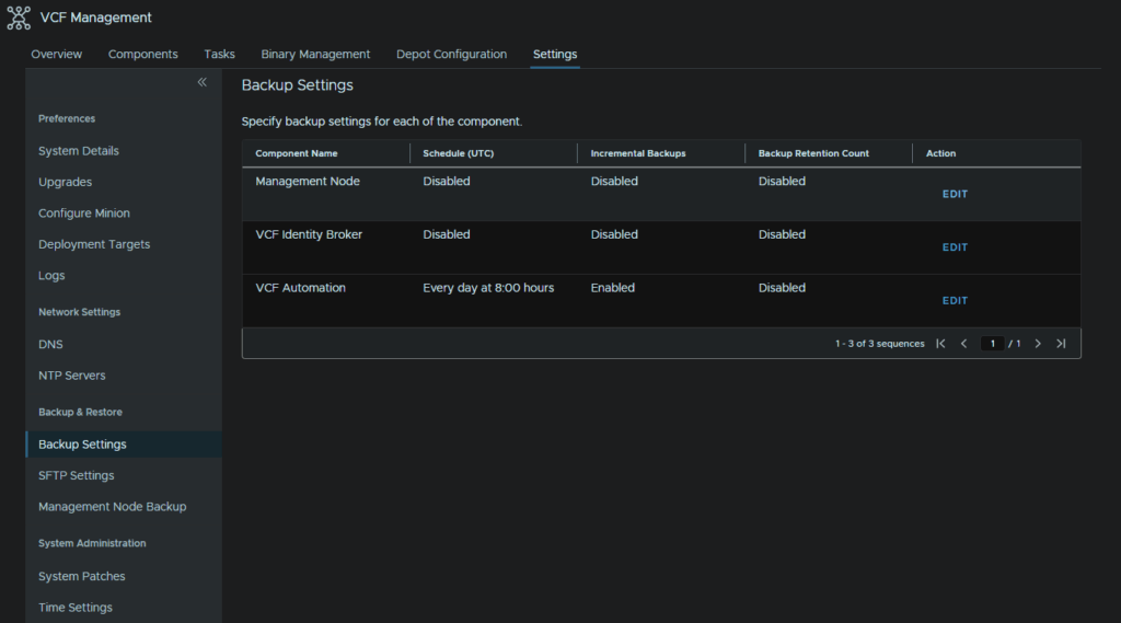
Set a time for a daily backup and enable the retention policy, 7 days is plenty and click Save
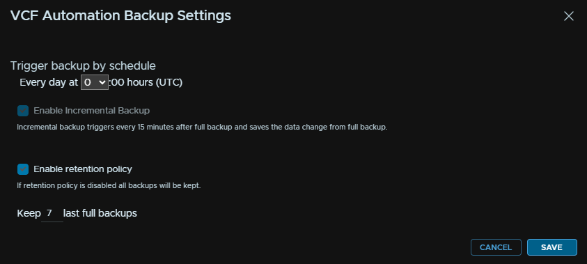
It should look like this
Unfortunately the config backups for fleet management are stored locally and oddly dont follow the SFTP setup, so I recommend also backing it up with your backup provider with the other VMs below
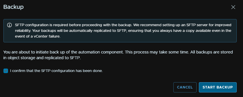
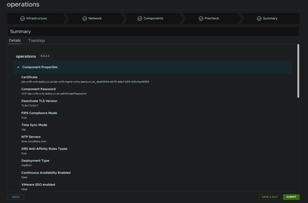
For VCF Automation to test that works, head to Components and click the automation component
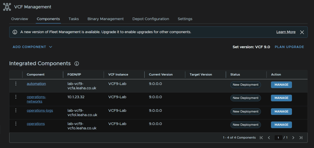
Click the three dots, then Backup And Restore/Backup
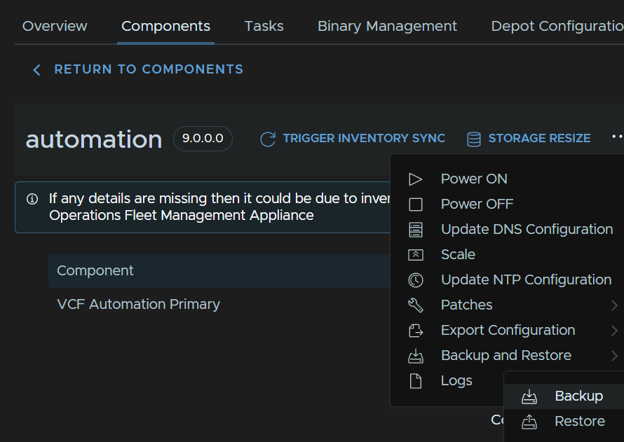
Check the box and click Confirm
For VMs to backup with your backup software that arent covered by these, you’ll need to add
- VCF Ops For Networks
- Fleet Management
- VCF Ops
- VCF Ops Collector
- VCF Ops For Logs
9 – Commissioning New Hosts
9.1 – Creating A Network Pool
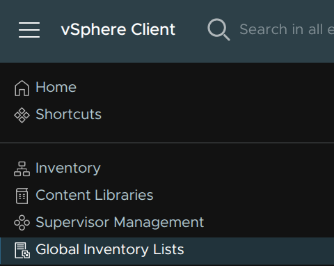
Open the management domain vCenter and click the three lines in the top left, then click Global Inventory Lists
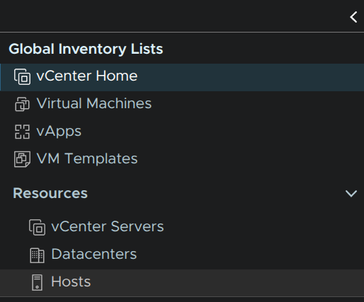
On the left, click Hosts
We first need a network pool, if you are expanding a cluster thats already been created, there will already be a pool that can be used, in that case you can skip this part, but if you are adding a workload domain a new pool will be required, for a new cluster you may or may not need a new pool
Pools must not have overlapping IP ranges
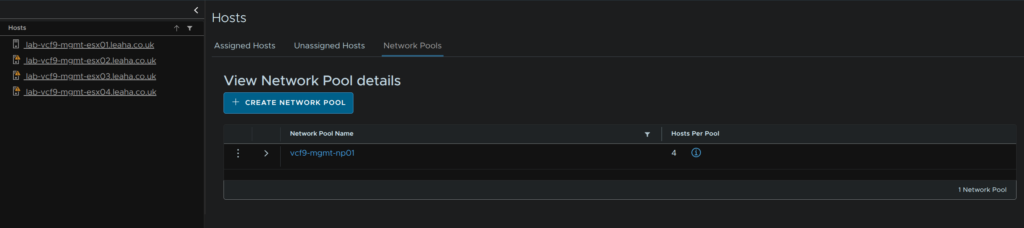
Click the Network Pools section and click Create Network Pool
This part will depend on what you are deploying storage wise, but you’ll pool for vMotion and one for your storage, for this cluster I am using vSAN, it also needs a name
Hosts will also need to be setup like in the ESX section
When you have your networks enter the VLAN, MTU, which likely is 9000, but this will match what you did in the deployment, then add the network, subnet mask, gateway, its worth noting here, neither of my networks actually have a gateway, then enter an IP range for hosts
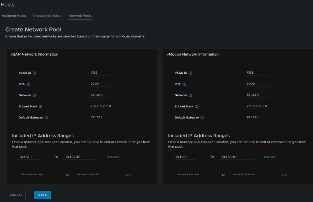
When you have the address ranges, you’ll need to click Add
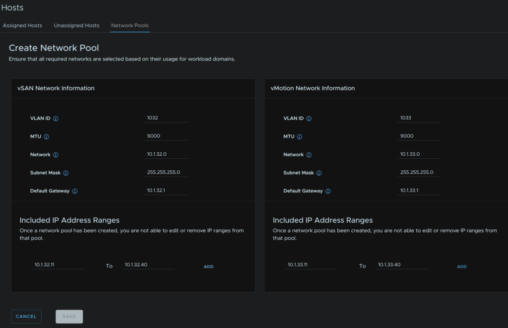
When you are done it should look like this, when you are happy, click Save
9.2 – Commissioning New Hosts
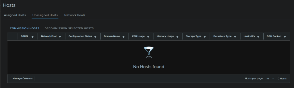
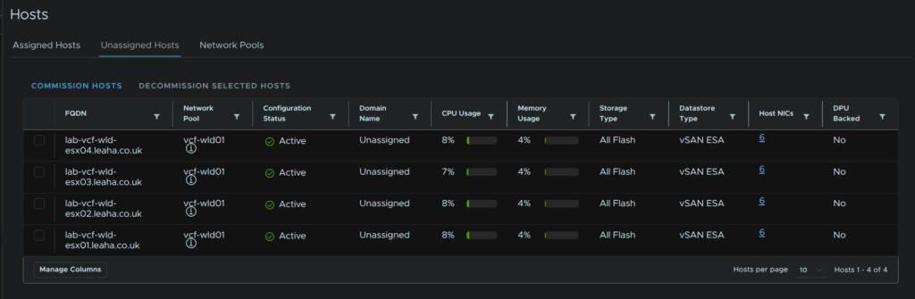
Then we need to commission a host, click Unassigned Hosts and click Commission Host
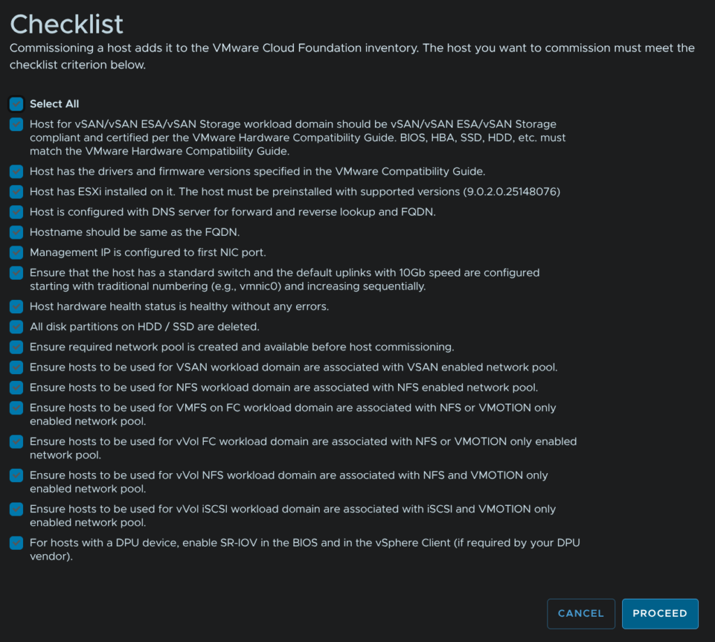
Check and prerequisites, you will need to select all before continuing
When you are happy click Proceed
Its worth noting 10GbE NICs are required for hosts in VCF 9
There is a workaround WilliamLam posted, which allows slower NICs, but should only be applied to lab environments, his article can be found here
But all you need to do is SSH into the SDDC Manager, switch to the root account with, su root, and run
echo "enable.speed.of.physical.nics.validation=false" >> /etc/vmware/vcf/operationsmanager/application.properties
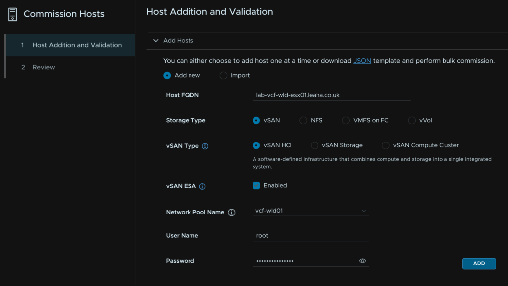
systemctl restart operationsmanagerAdd your host FQDN, select the storage type, select the network pool we created earlier, enter the root credentials and click Add
If your hostname is over 15 characters click Acknowledge, this can be ignored as hosts shouldnt be domain joined
Repeat for all hosts to commission, a non vSAN cluster requires at least two hosts, while vSAN requires at least three hosts
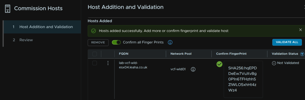
At the bottom, click the toggle to confirm the fingerprint and click Validate All
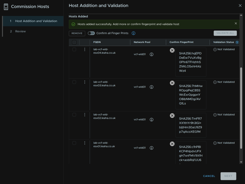
Then click Validate All
Once thats validated, click Next
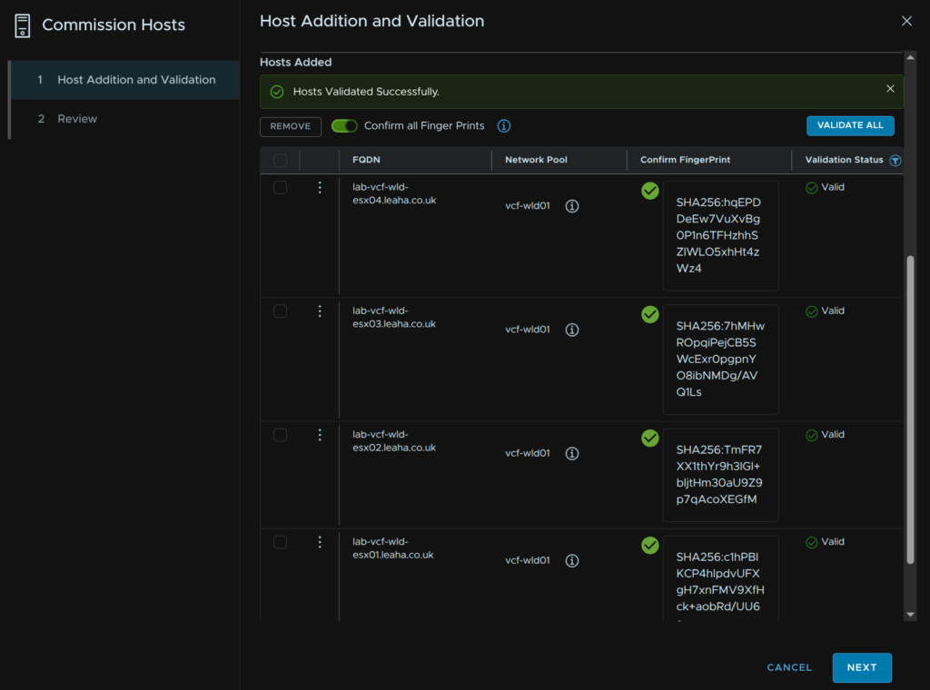
Then click Commission
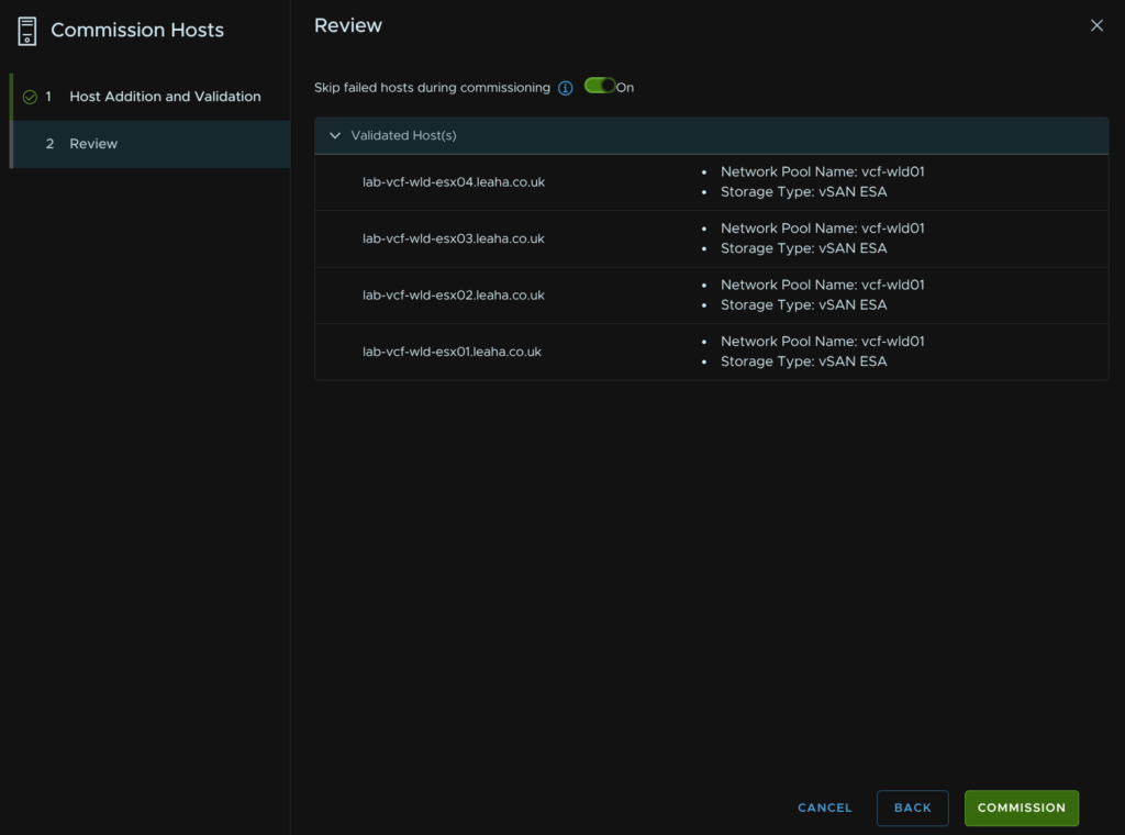
When its done it should look like this
10 – Importing An Image
This step has been added here as its a prerequisite for adding workload domains and new clusters to existing domains
Before we setup an image, ensure you have run the depot fix for the VCF environment and management domain, else creating images wont work properly, more info can be found here
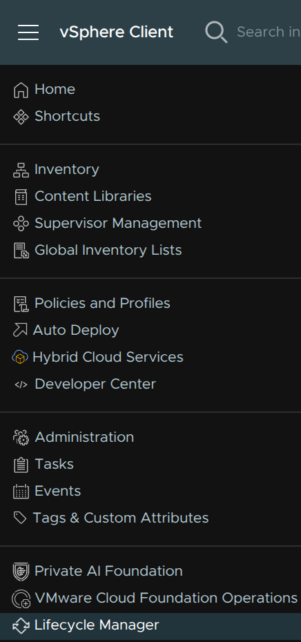
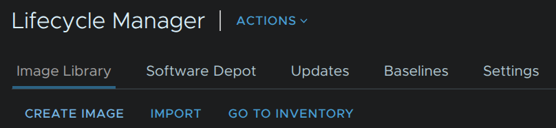
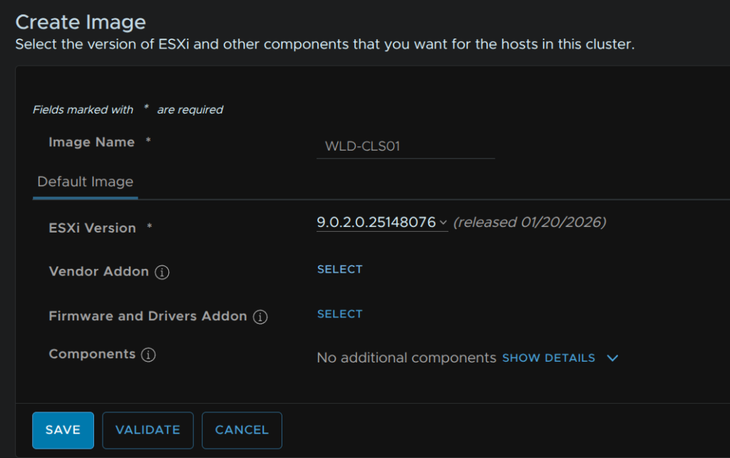
We first need an image for our new hosts, in the management domain vCenter, click the three lines in the top left and click Lifecycle Manager
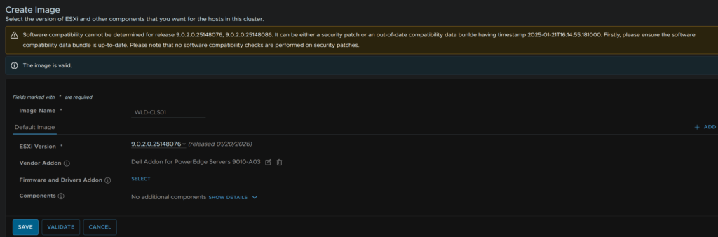
Click Create Image
Give it a name and select the release matching the ESX hosts current version
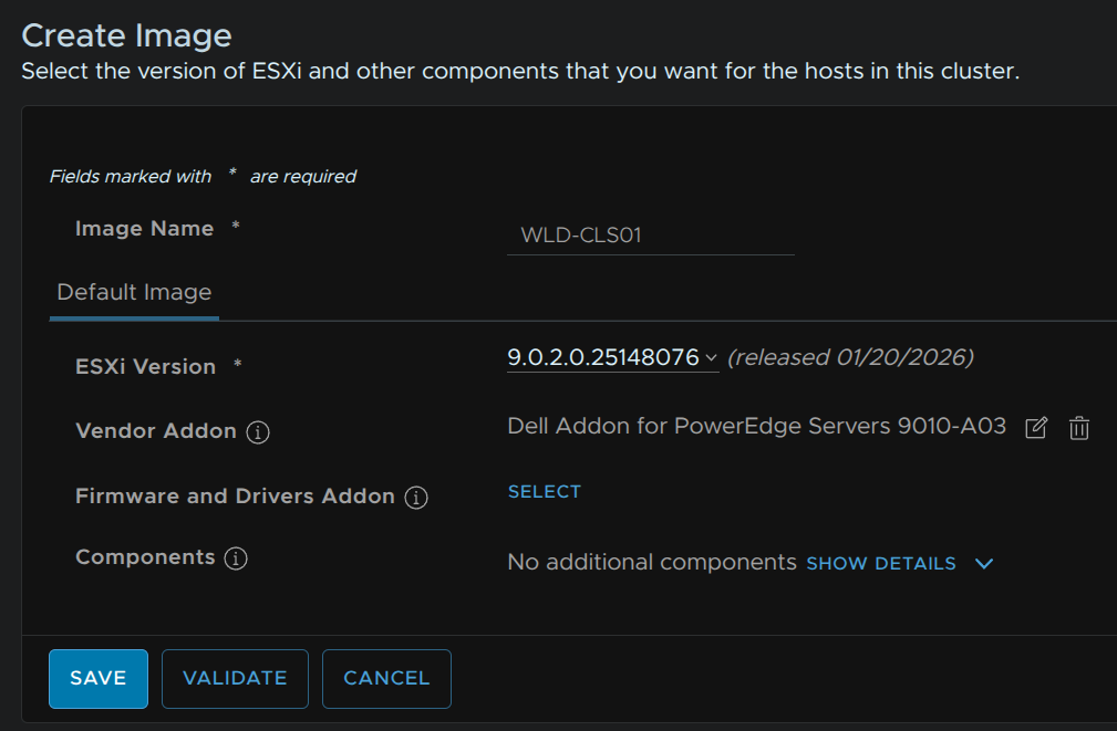
Then on vendor addon, click Select
We have the following for Dell
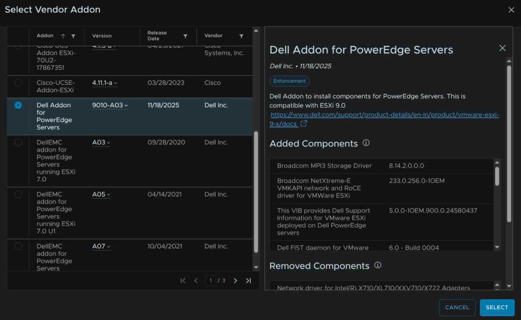
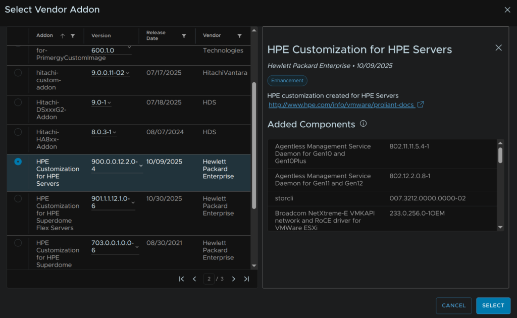
And this for HPE, when you have the one you want, click Select
You can also add addition components if you need, like GPU drivers, they will need manually uploading to the lifecycle manager
When you are happy, click Validate and when its valid
You may get an error if this matches the management domain image, if you have this skip this step
We can ignore the warning in the case and click Save
Now in VCF Operations, click Fleet Management/Lifecycle, expand VCF Instances, select your VCF Instance and click Image Management/Import Image
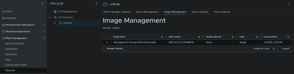
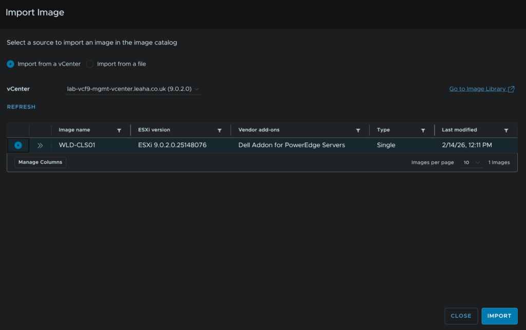
The vCenter should be auto populated as the management domain vCenter, then click the image and click Import
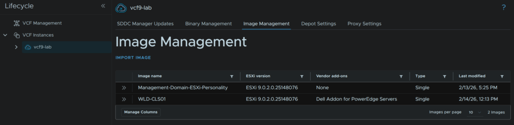
When its done you’ll need to refresh your page and you’ll see the image in there
11 – Deploying A Workload Domain
Its worth noting I have gone through the wizard for deploying a new workload domain, NSX networking, the supervisor and licensing have been excluded as the are the same as the processes above in sections 6.2, 7 and 8.3 respectively
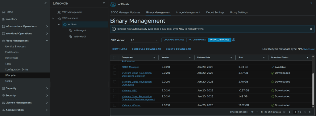
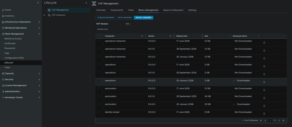
This also assumes the binaries are left over from the deployment and the workload domain is the same version, if not you will need to download binaries in advanced from VCF Operations by clicking Fleet Management/Lifecycle, expand VCF Instances and click your VCF Instance, then click Binary Management/Install Binaries
Before starting you will need to have completed section 9 and 10 so there are enough hosts in the inventory and an image is available
Networking wise, vCenter and NSX manager components are deployed directly into the management domain and use the same port group that the management domain vCenter and NSX managers are using, so bare in mind the FQDNs for these appliances for the workload domain must resolve to that network else you will run into issue, these systems can run perfectly fine over L3 in a separate environment, services like NSX Edges and the Supervisor will be hosted within the workload domain
The first workload domain you have must have its own NSX instance, you cannot use the management domain NSX instance, subsequent workload domains can be configured to use the first workload domains NSX instance, and this is important for sizing
All prerequisites from the introduction deployment apply here only the required VLANs are slightly different
11.1 – Starting The Workflow
This will need to be done via VCF Operations, click Inventory, by default you will be on the simplified view, so click Details View
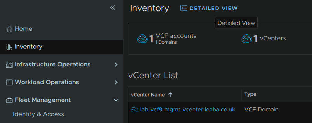
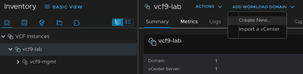
Expand VCF Instances and select your VCF instance, then click Add Workload Domain/Create New
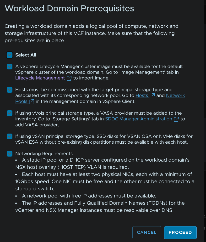
Check the prerequisites and click Proceed
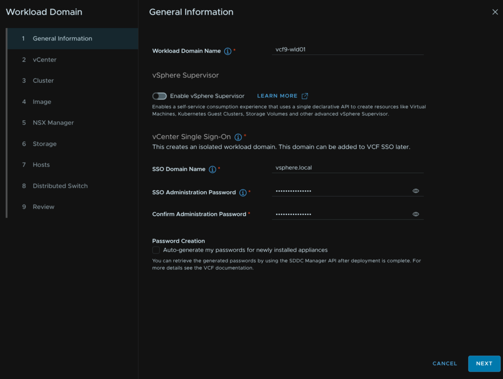
11.2 – General Information
Give the workload domain a name, we can disable the supervisor for now, it can be manually configured later like in section 7
Provide an SSO domain name for the vCenter, I would stick with the default vsphere.local, I then unchecked the Password Creation box so we can manually set passwords
When you are happy click Next
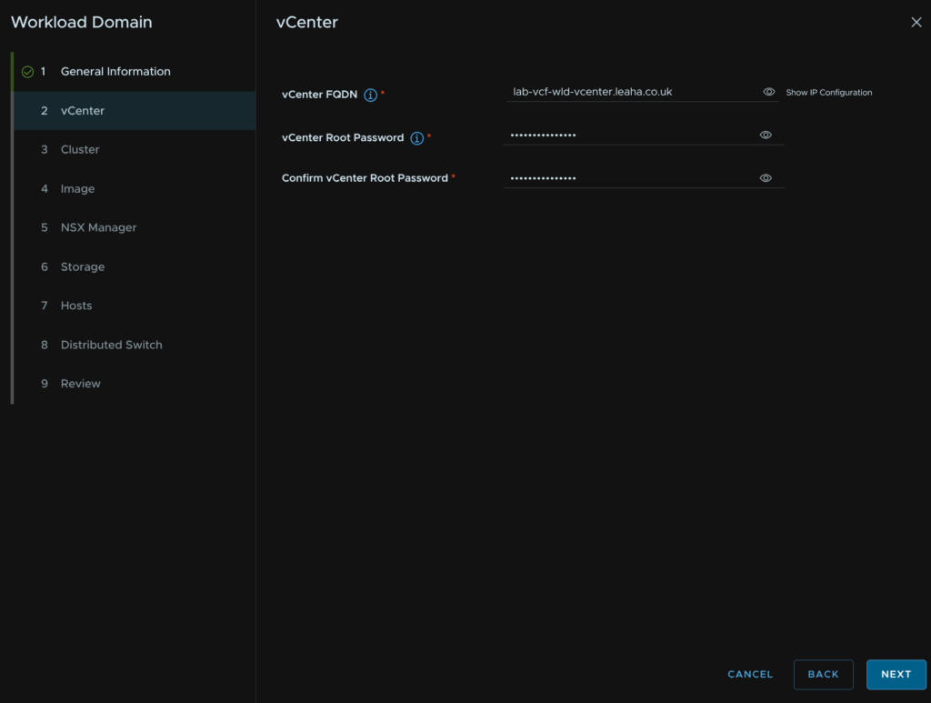
11.3 – vCenter
Add the vCenter FQDN and root password, then click Next
This will default to a large vCenter with 8vCPU and 30GB RAM
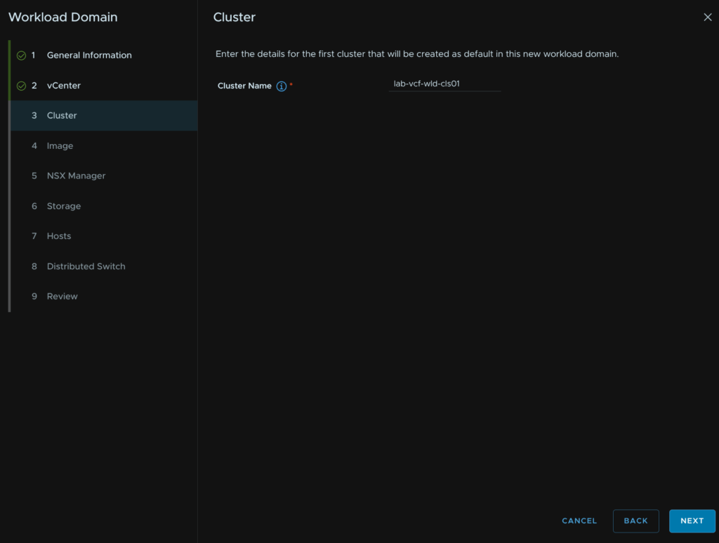
11.4 – Cluster
Give the cluster a name and click Next
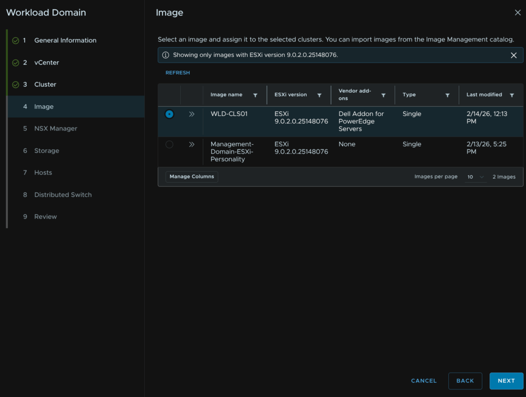
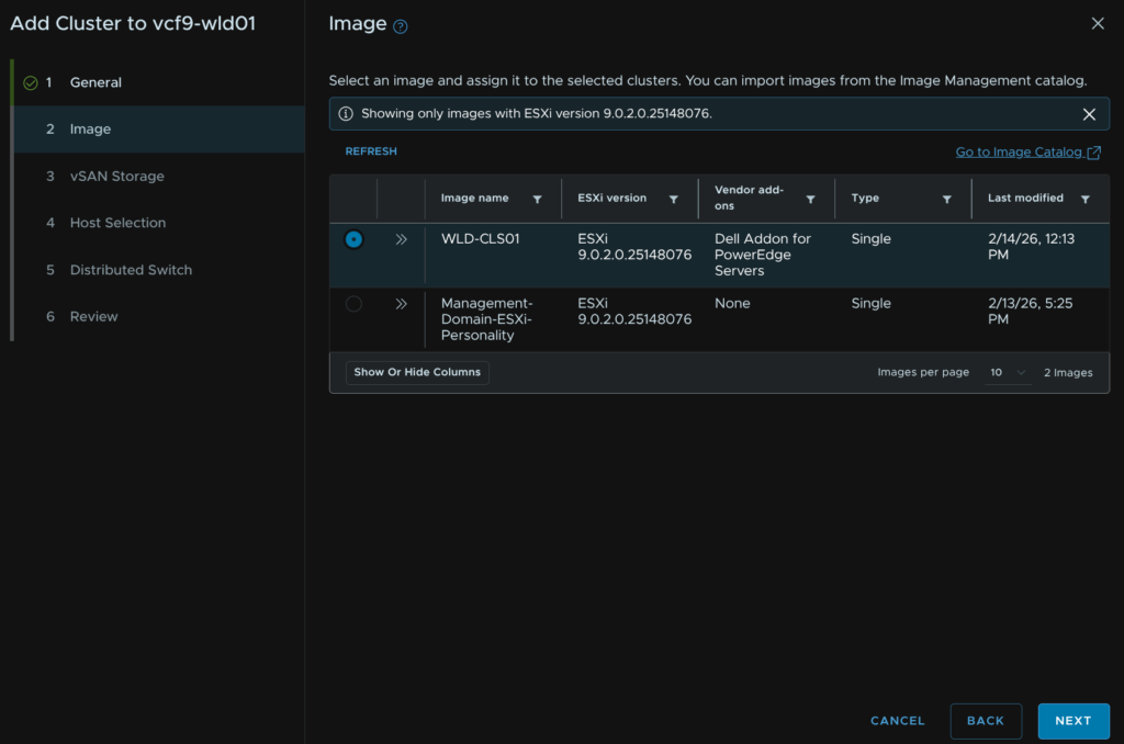
11.5 – Image
Select our new cluster image and click Next
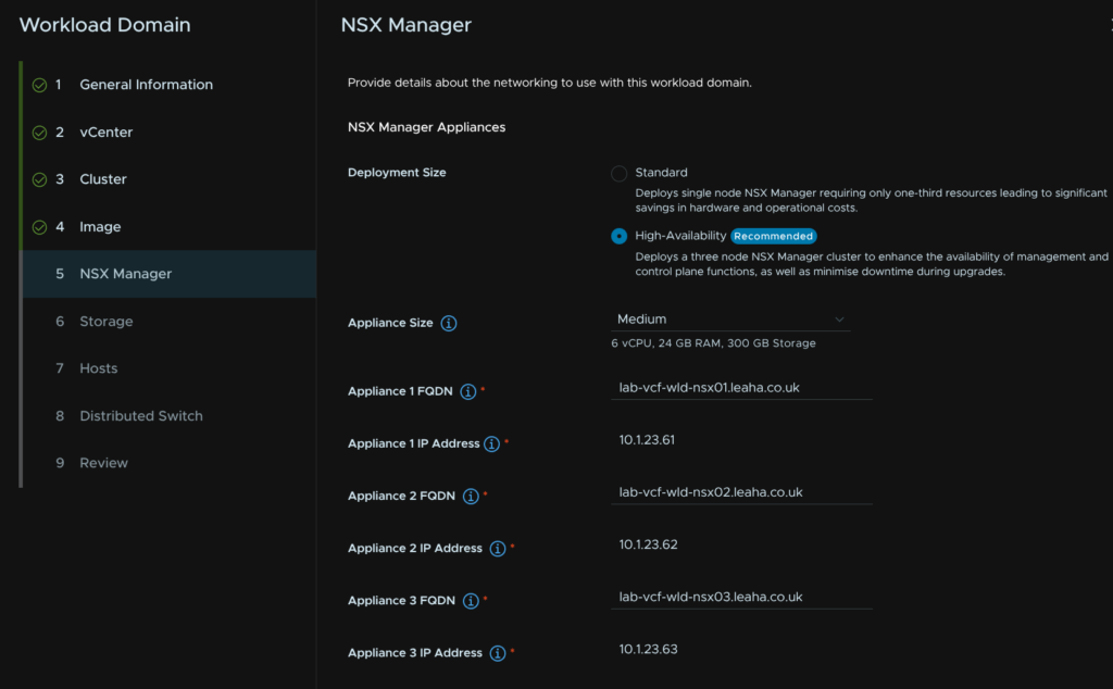
11.6 – NSX Manager
We then need to setup our NSX instance, I would always recommend HA in production, then select the size, I am using Medium
| Medium | Large | |
| Host Maximum | 128 | 1,024 |
| vCPU | 6 | 24 |
| RAM | 24 | 48 |
| Maxium Compute Managers | 2 | 16 |
We then need to add the FQDNs of the three target NSX manager nodes, the IP addresses will be populated automatically from a DNS lookup
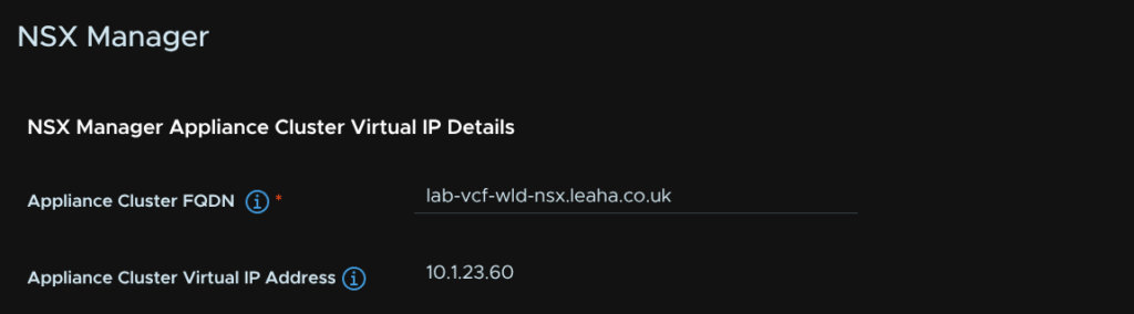
Next enter the NSX instance VIP address FQDN
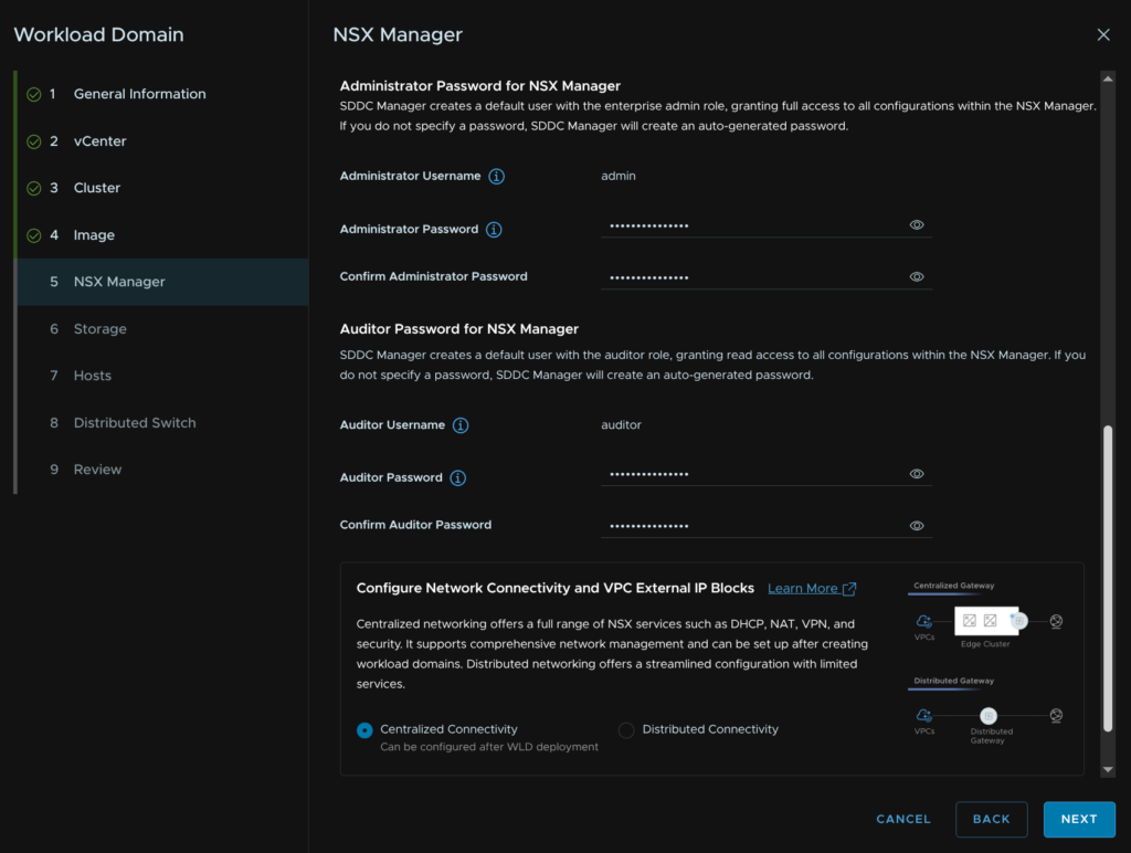
Next add a password for the admin and auditor accounts, and select the VPC network connectivity topology, generally, you’ll always want to go with Centralized, this uses NSX Edges and gives you full functionality
Then click Next
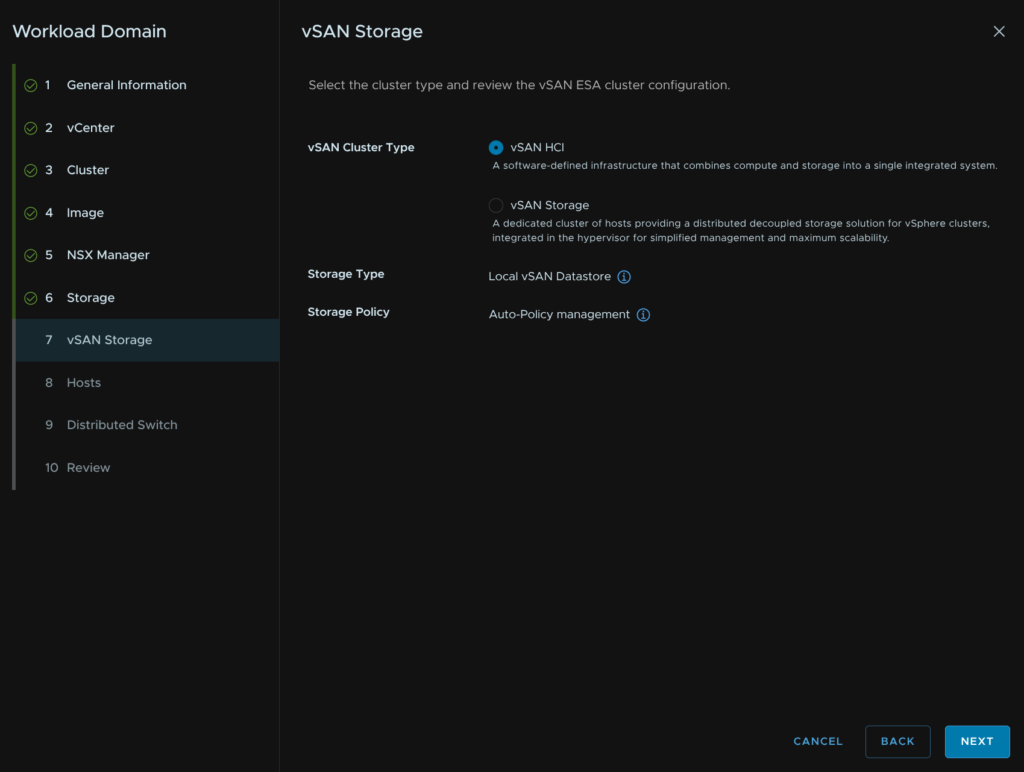
11.7 – Storage
We then need to choose our storage type, I have planned for vSAN ESA, so I select that and clicked Next
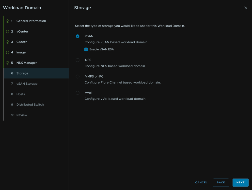
The default vSAN HCI is what you likely want, if you are unsure use this option, if you know you need a vSAN storage cluster select that and click Next
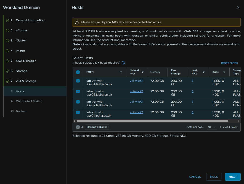
11.8 – Hosts
We then need to select our hosts, I am using all four I added earlier, then click Next
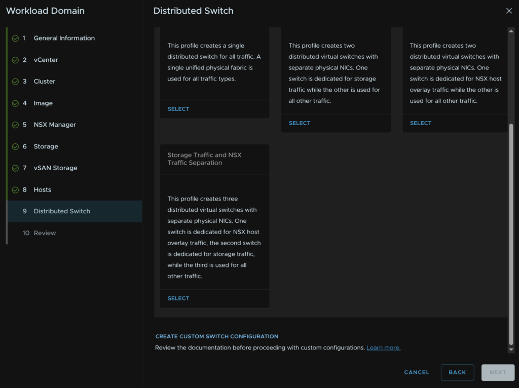
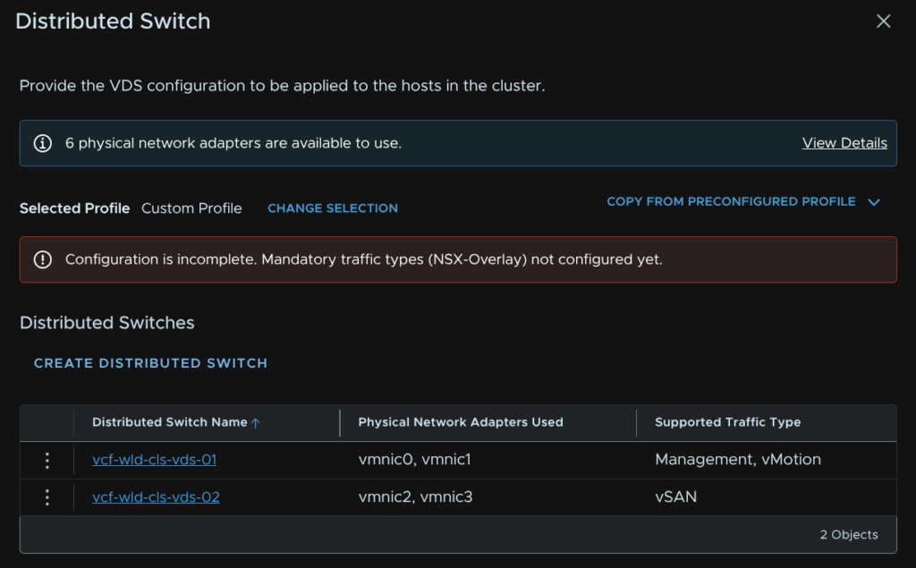
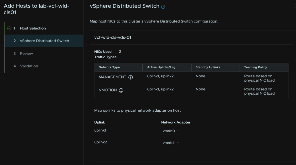
11.9 – Distributed Switches
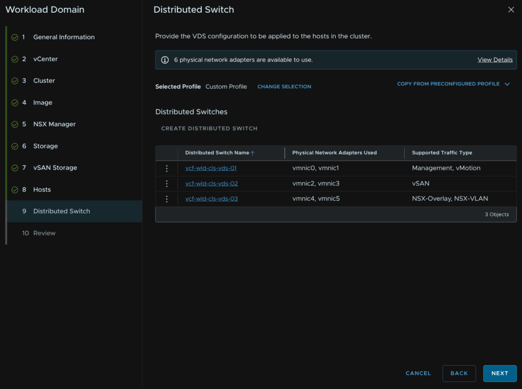
We then need to select our networking topology, I recommend 6 NICs using the storage and NSX traffic separation, but if you have only 4 NICs, what I would consider to be the minimum, use storage separation
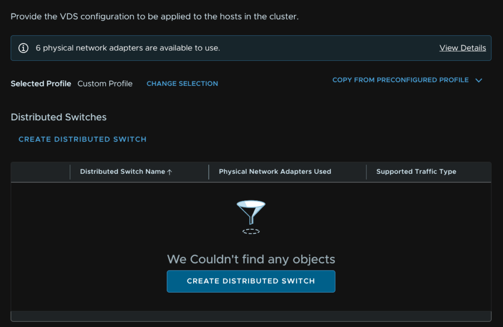
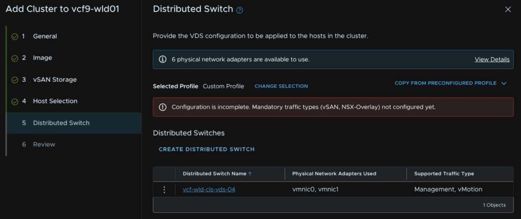
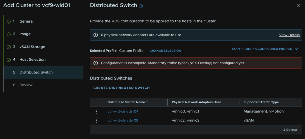
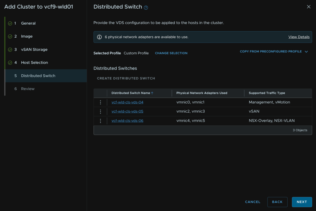
Now, while we have the defaults, this doesnt actually let you edit the settings, and the issue there is the NSX TEP addresses will be using DHCP when we want an IP pool like the management domain during the deployment, so click Create Custom Switch Configuration at the bottom, and we will manually set up the topology
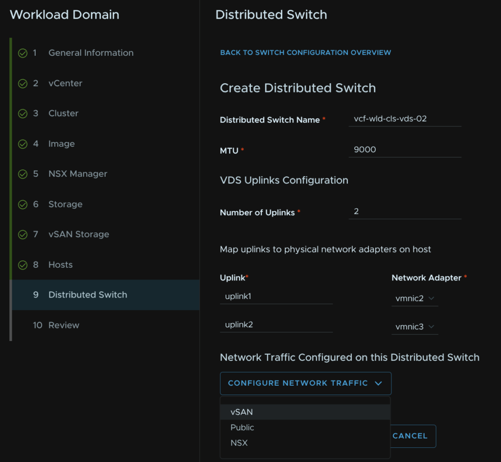
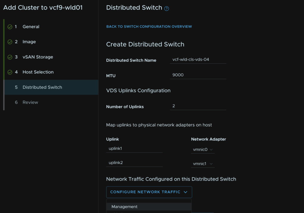
Click Create Distributed Switch
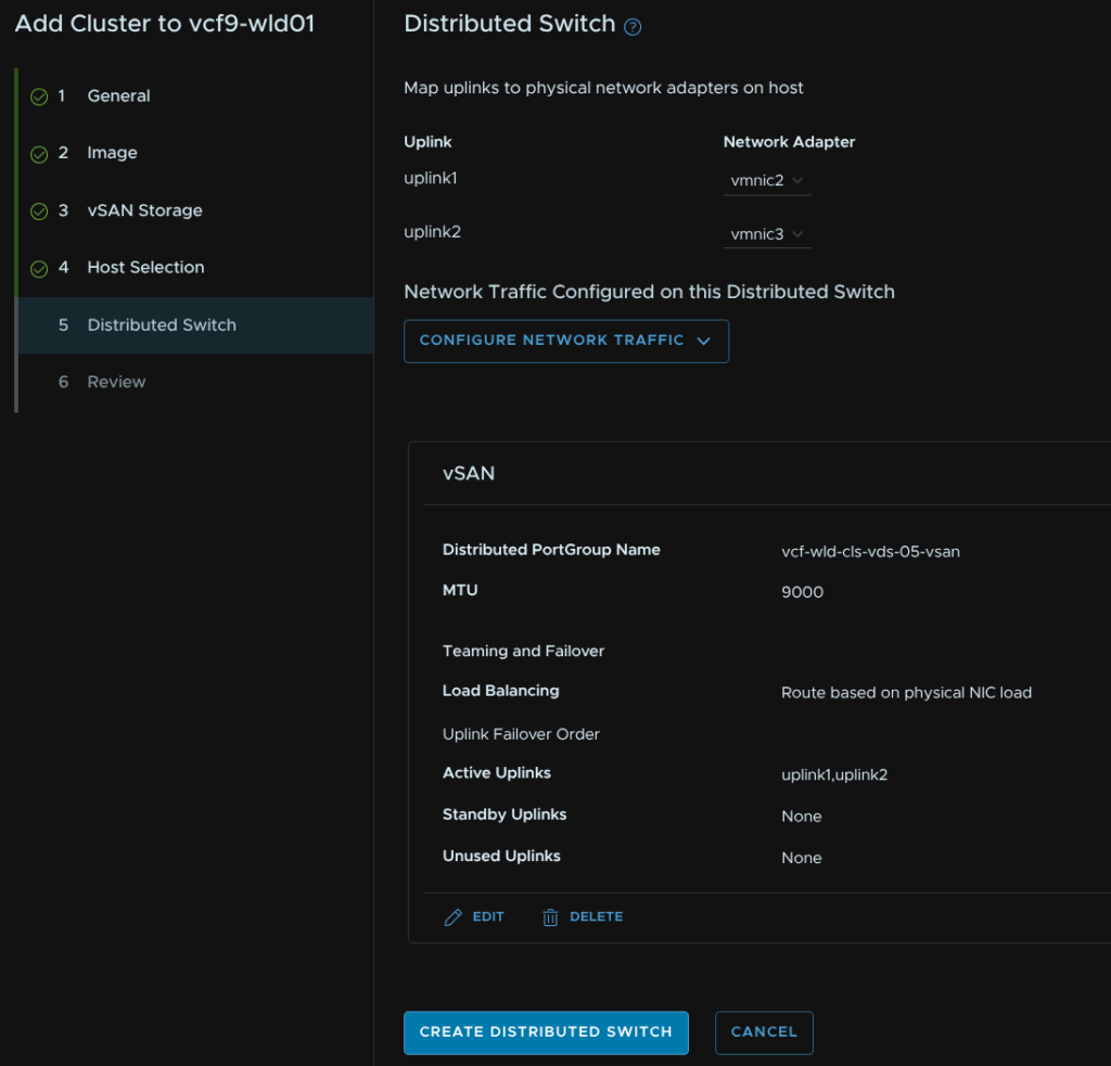
Add a VDS name and set the MTU, this should be 9000, but in line with what was set for the management domain, we need 2 uplinks, select the vmnics you want to use then click Configure Network Traffic Type/Management
One of these uplinks should be bound to the vSwitch on the default ESX install
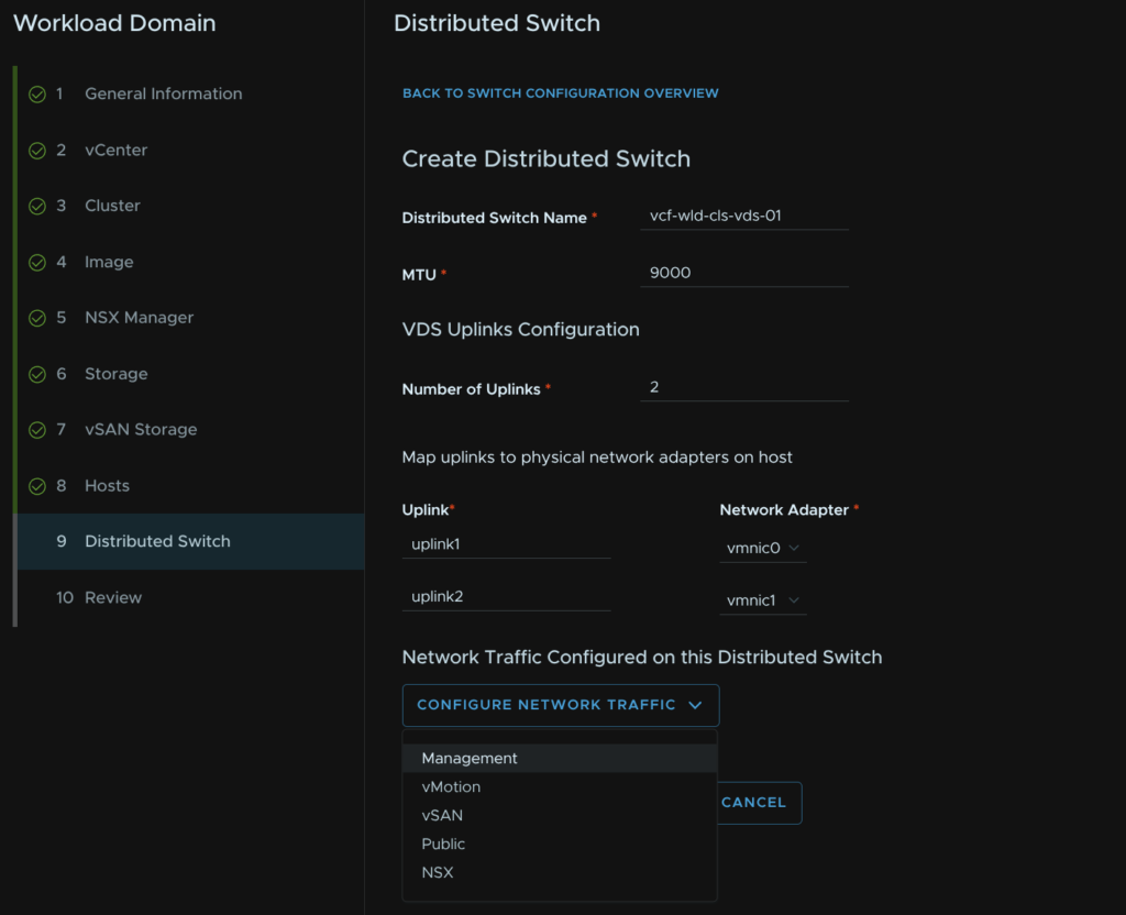
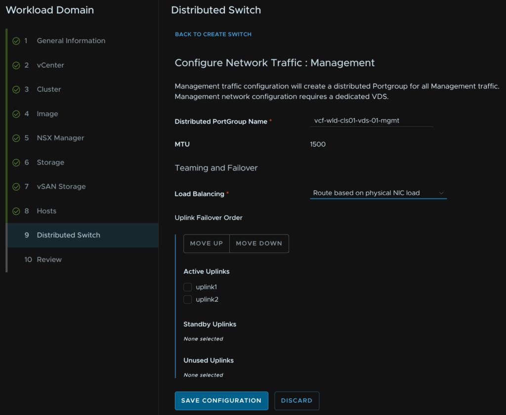
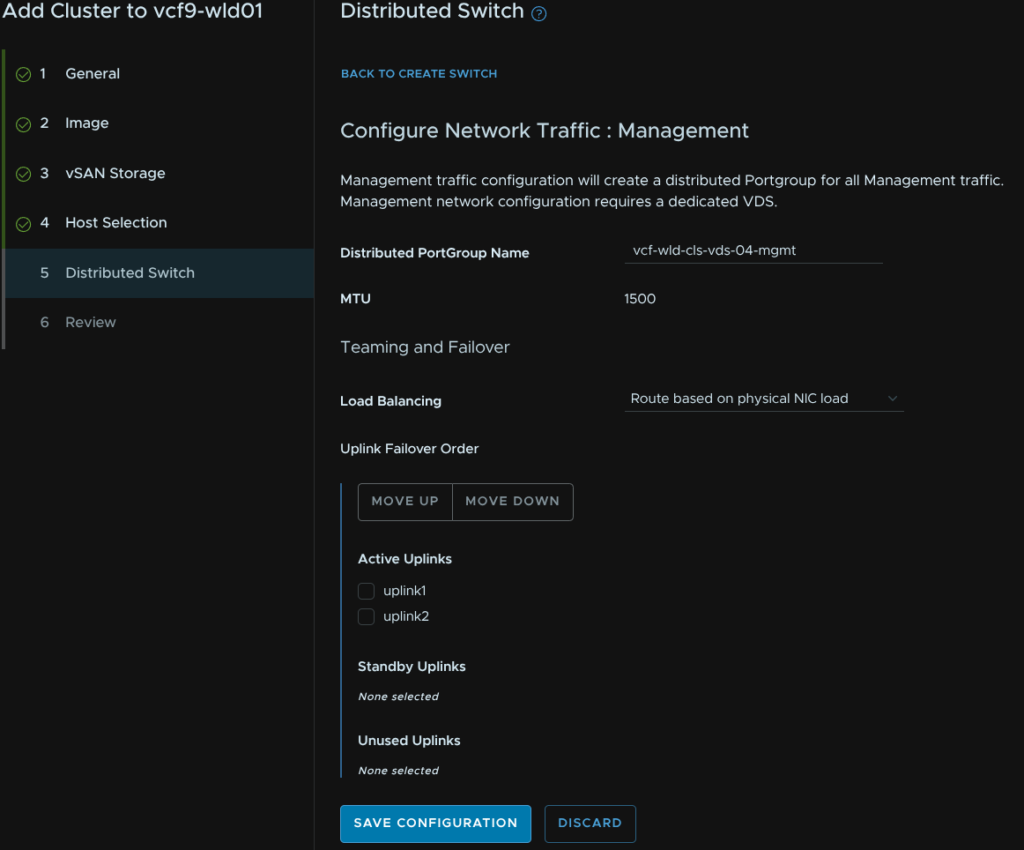
Give the port group a name and select the load balancing policy of route based on physical NIC load then click Save Configuration
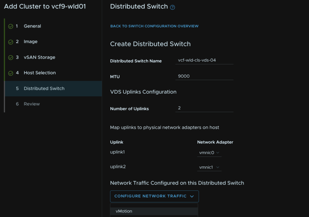
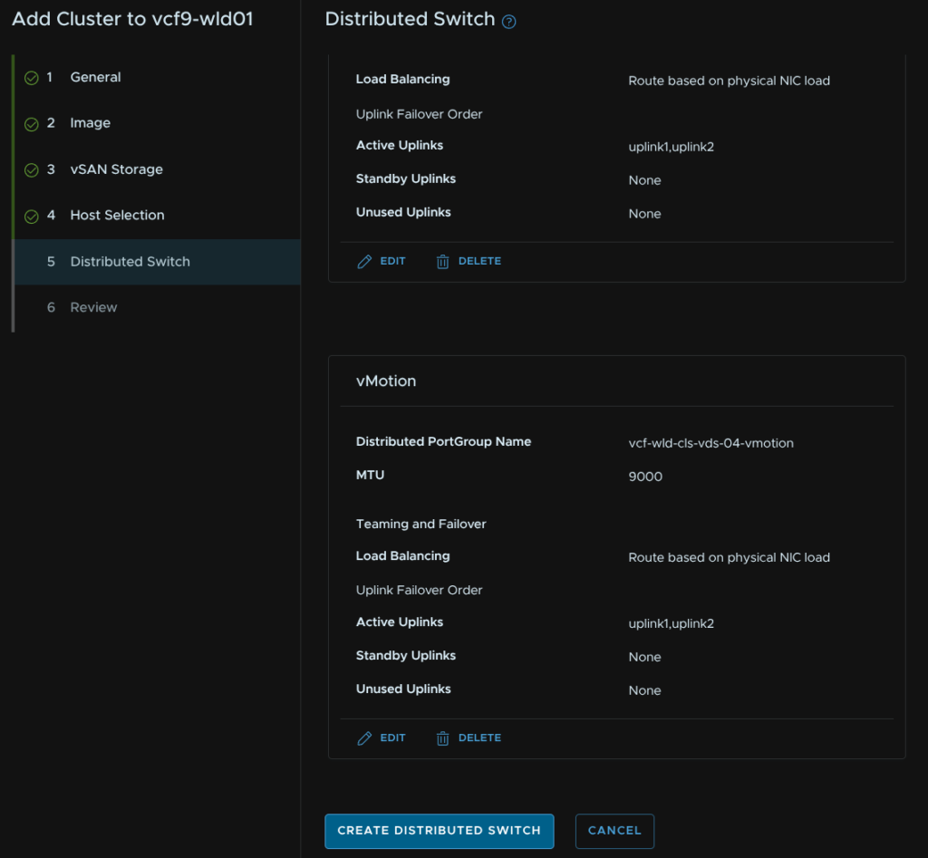
Click Configure Network Traffic/vMotion
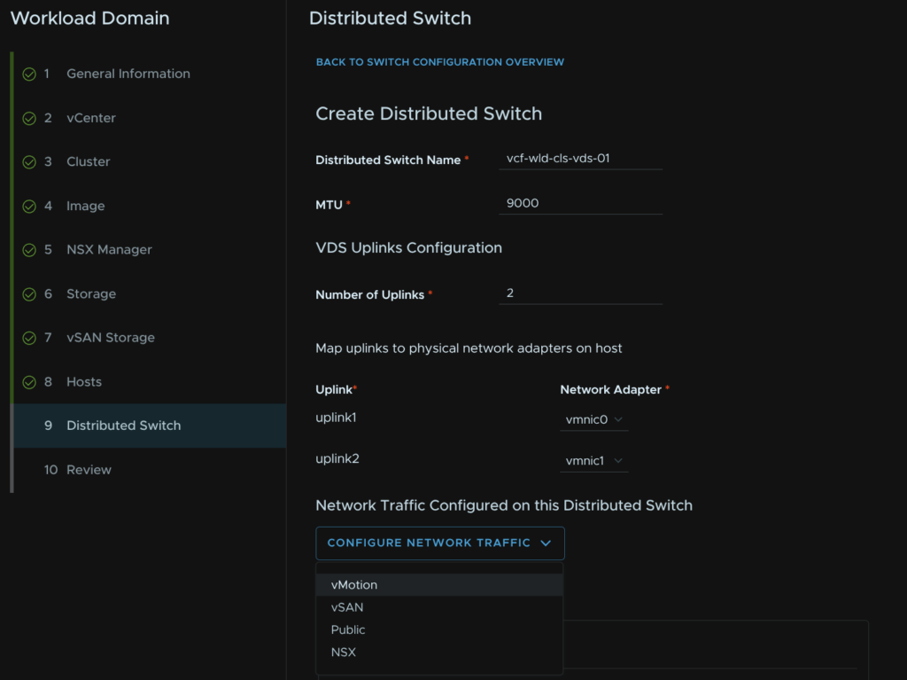
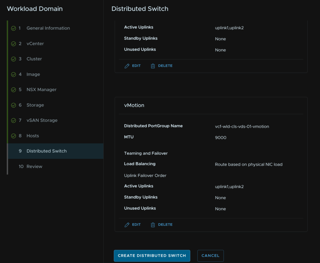
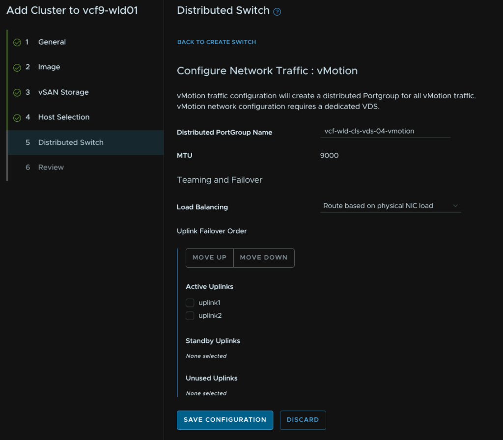
Give the port group a name and select the load balancing policy of route based on physical NIC load then click Save Configuration

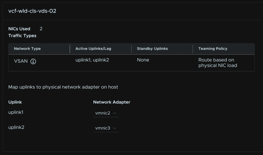
Scroll to the bottom and click Create Distributed Switch
Click Create Distributed Switch
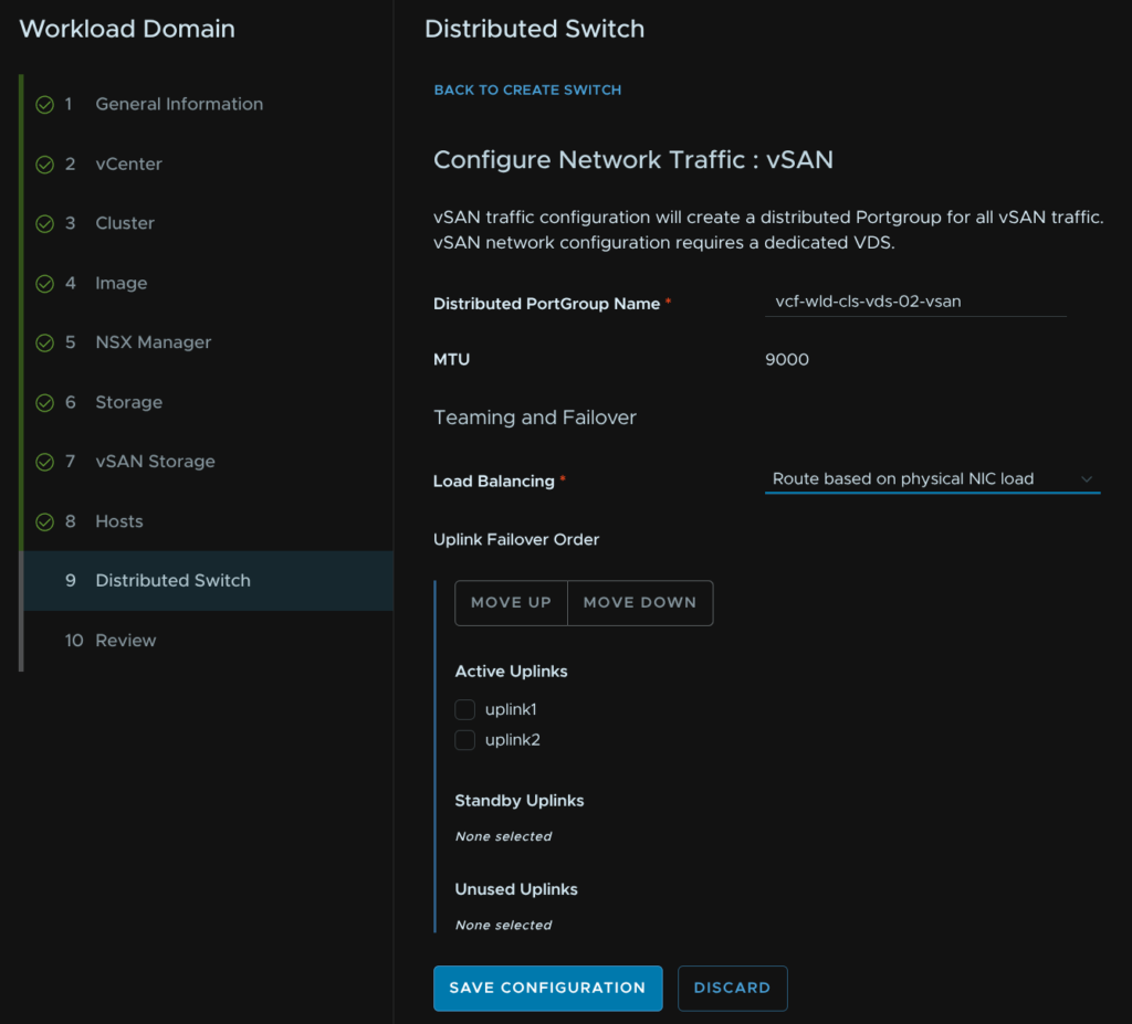
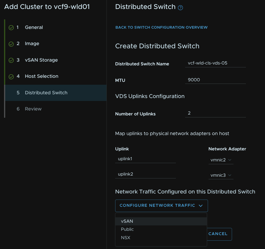
Give the VDS a name, set the MTU the same, which should be 9000, select the two uplinks you want to bind for storage and click Configure Network Traffic/vSAN
If you chose NFS configure that here
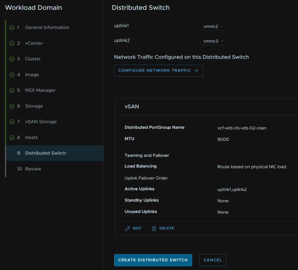
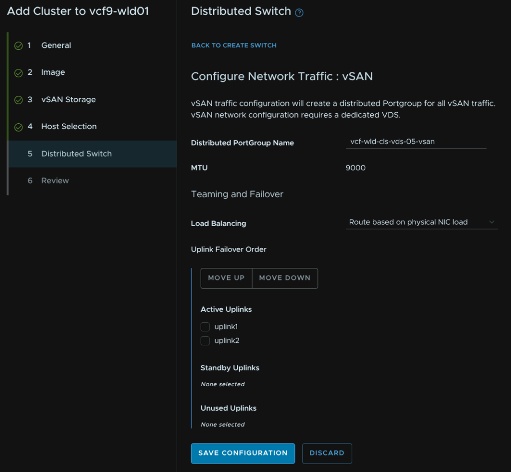
Give the port group a name and set the same load balancing option then click Save Configuration
Then scroll to the bottom and click Create Distributed Switch
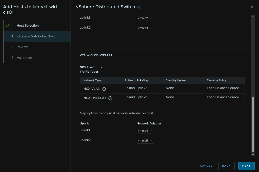
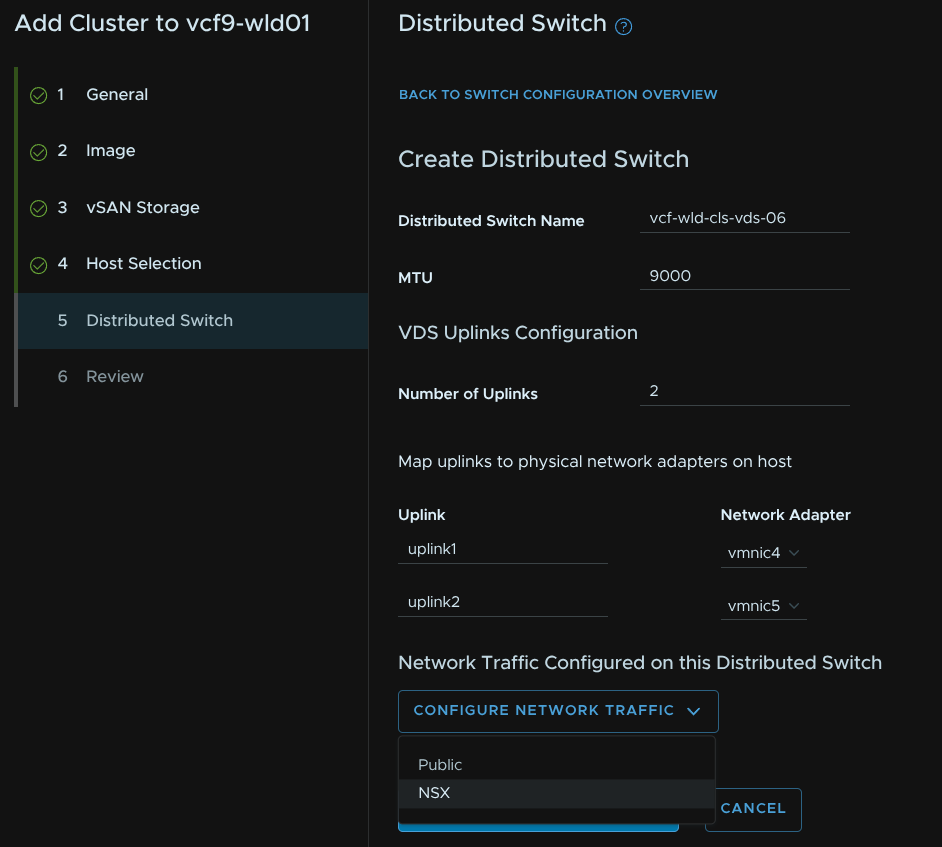
Click Create Distributed Switch one last time
Give the VDS a name, set the MTU to the same, at 9000, then add the remaining uplinks, then click Configure Network Traffic/NSX
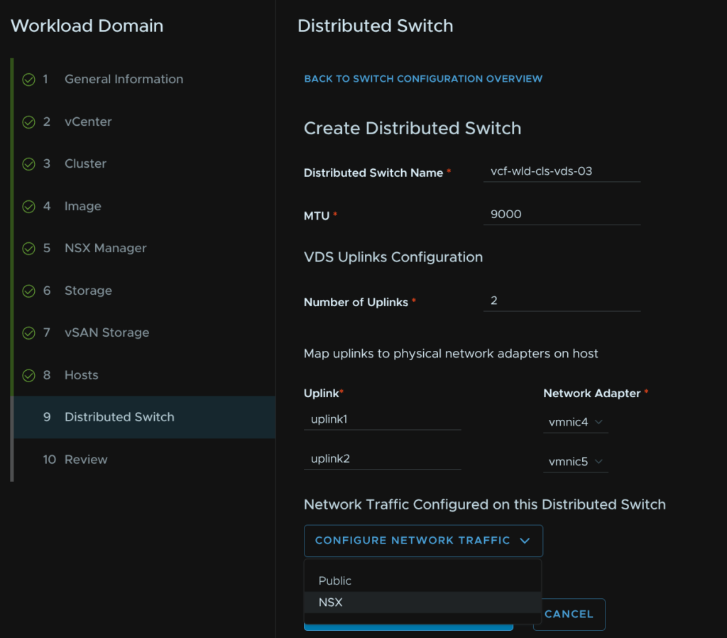
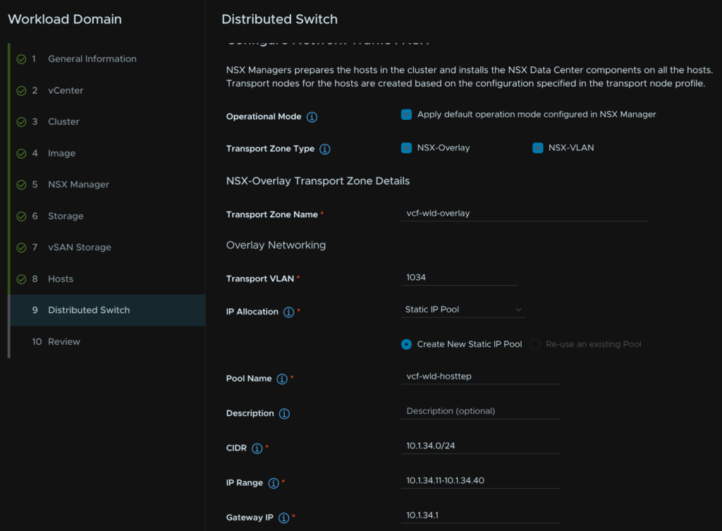
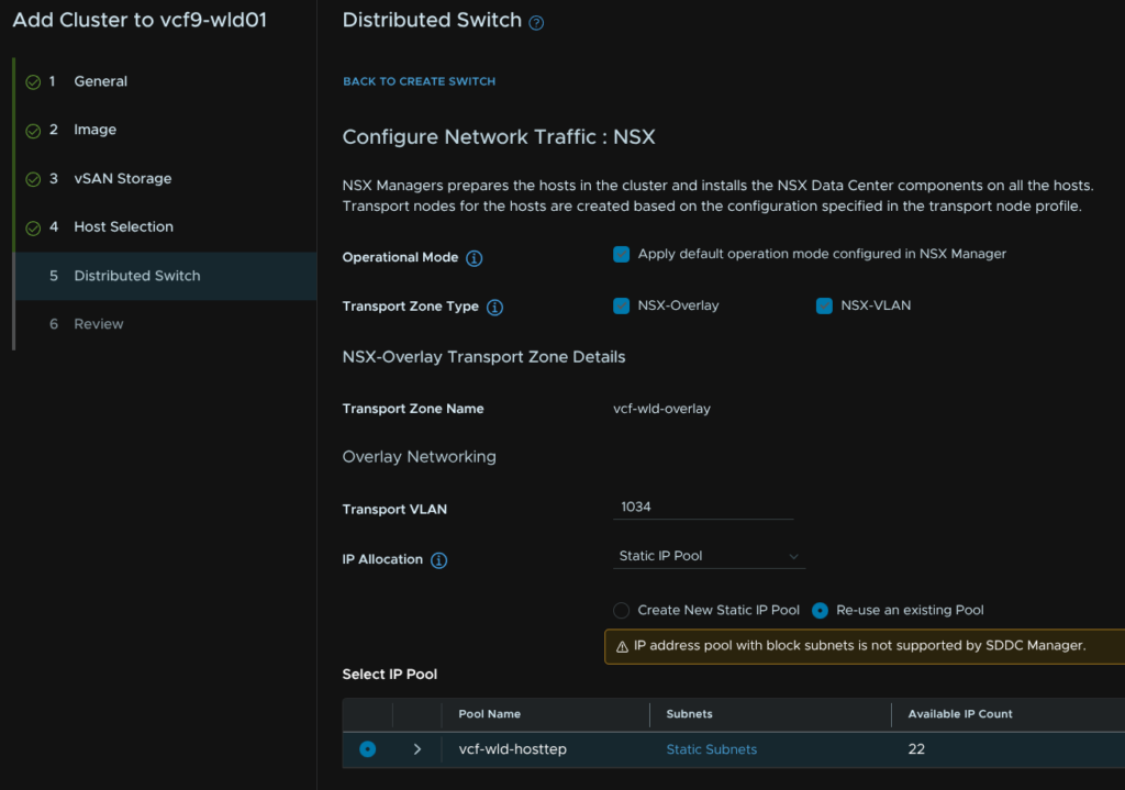
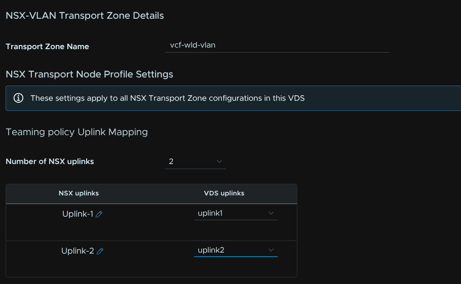
Leave the default boxes checked, all three should be, give the overlay transport zone a name, add the host TEP VLAN as the Transport VLAN, set the IP Allocation to Static IP Pool and create a new pool
Then give the pool a name, set the CIDR, IP range and gateway
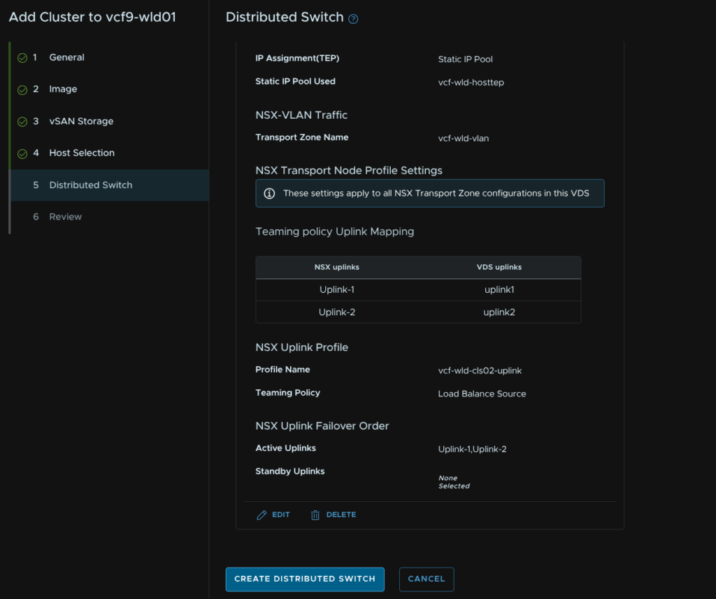
Give the VLAN transport zone a name, the uplink number should match the number on the VDS, in our case, 2, and set the NSX and VDS uplinks to match
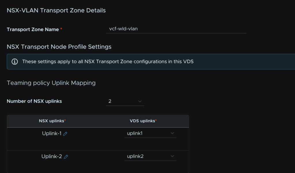
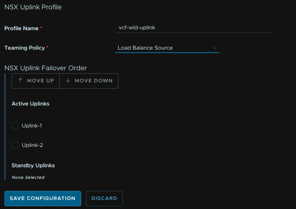
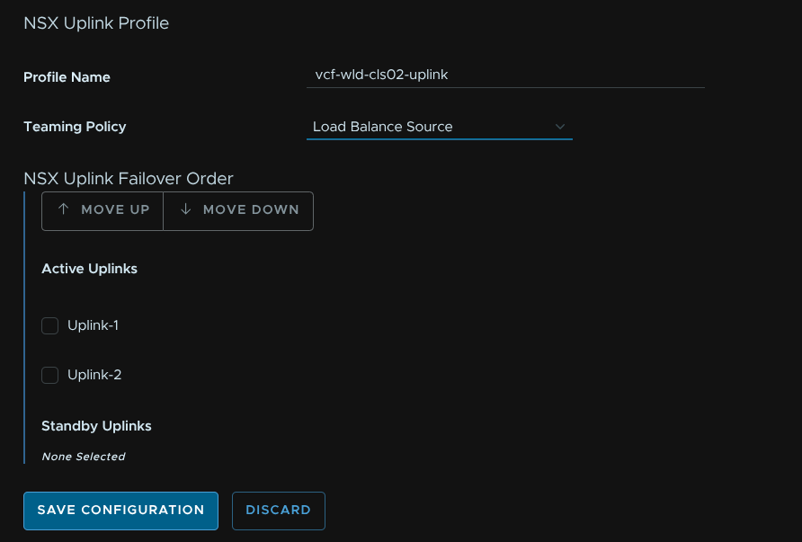
Give the NSX uplink profile a name and set the Teaming Policy to Load Balance Source and click Save Configuration
Scroll down and click Create Distributed Switch
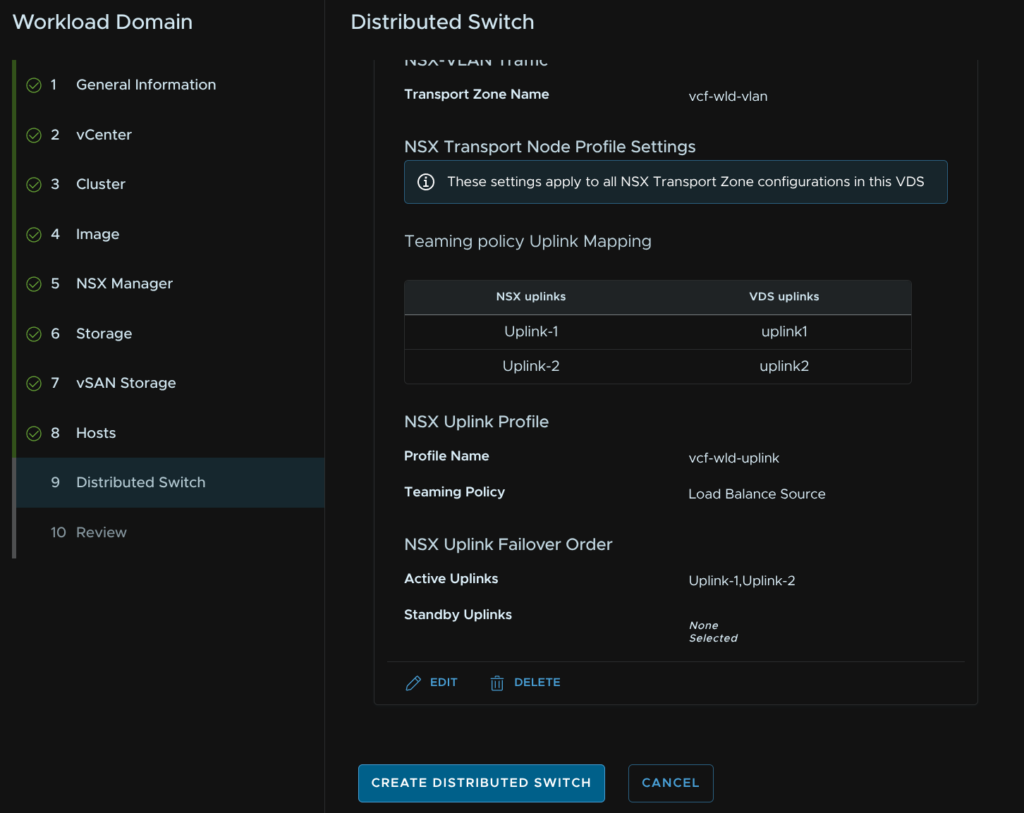
Then click Next
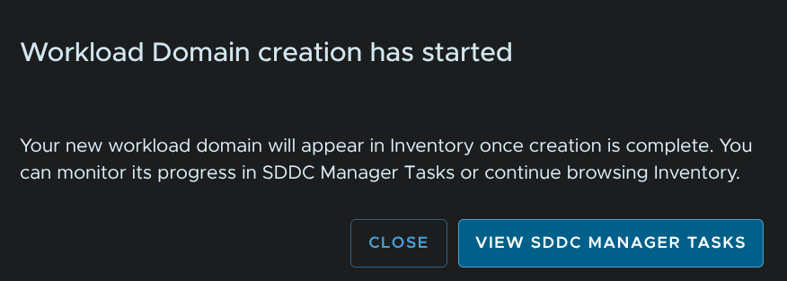
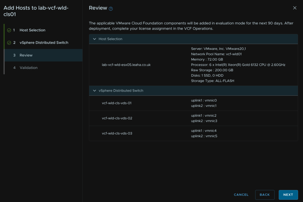
Review all the info and when you are happy click Finish
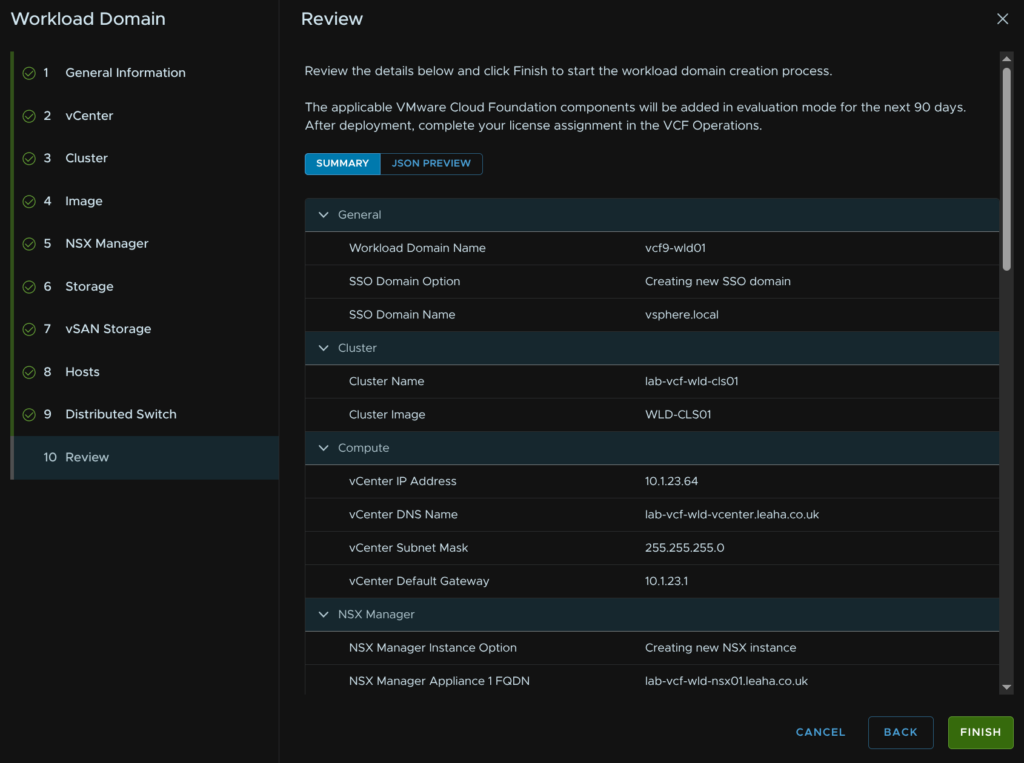
We can click View SDDC Manager Tasks on the pop up to track the progress
11.10 – Deploying A Collector
The default workload domain workflow doesnt deploy a collector as part of it, you can either use the collector in the management domain or you can deploy one to the cluster, I would recommend each workload domain has its own collector so thats what we will setup now
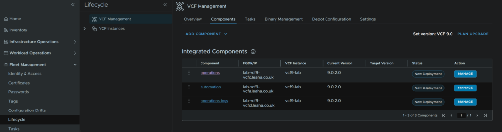
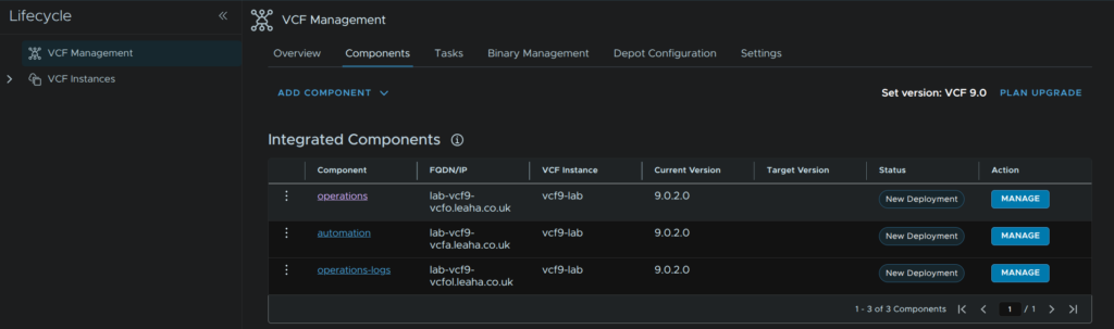
We can do this from within VCF Operations, head to Fleet Management/Lifecycle/VCF Management/Components and click the operations components
Click Add Node
Then click

When thats done click back to the Components view

Click the operations component again
Then click Add Nodes

Now click Proceed

This should all be pre populated, click Next
Click Next again, this should all populated again
Click Add Password
Give the password a name, this will be for the root password, and add a new password, then click Add
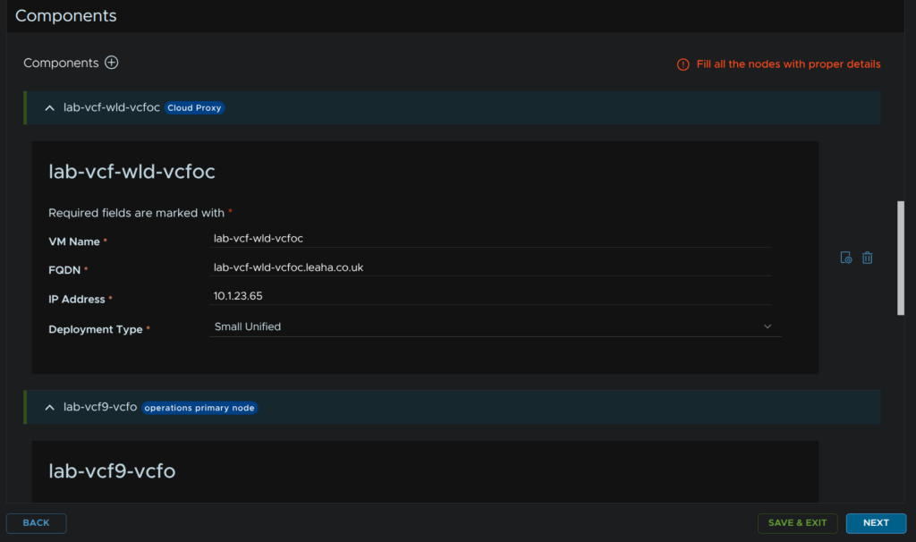
Scroll down to Components and click the + then click Cloud Proxy
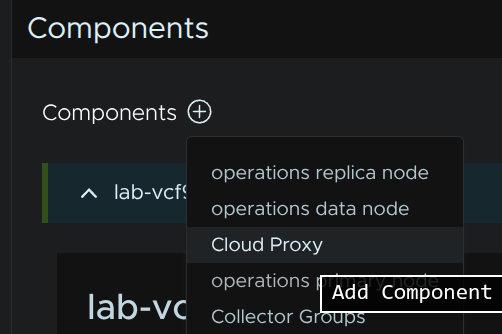
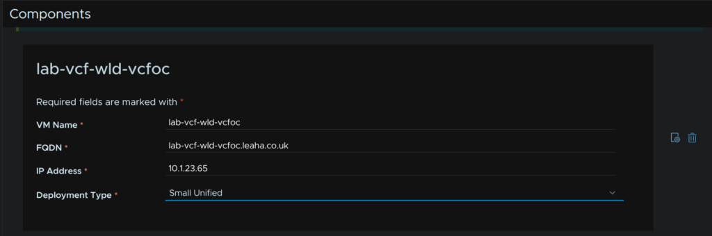
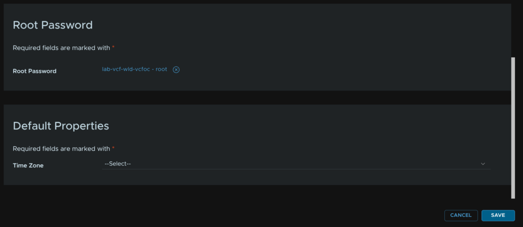
Enter a VM name, FQDN IP address and set the size, we want a unified proxy, small is fine for up to 16k VMs, standard does up to 80k, then click the setting icon, next to the trash can icon, on the right
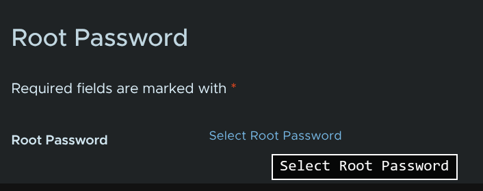
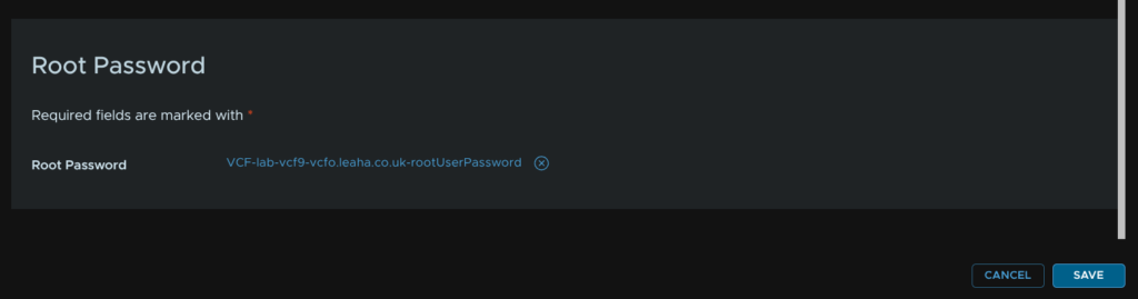
Scroll down to Root Password and click Select Root Password
Select our new password
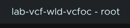
Then click Save
Then click Next
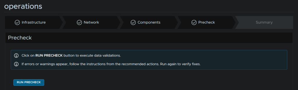
Then click Run Precheck
When thats passed, click Next
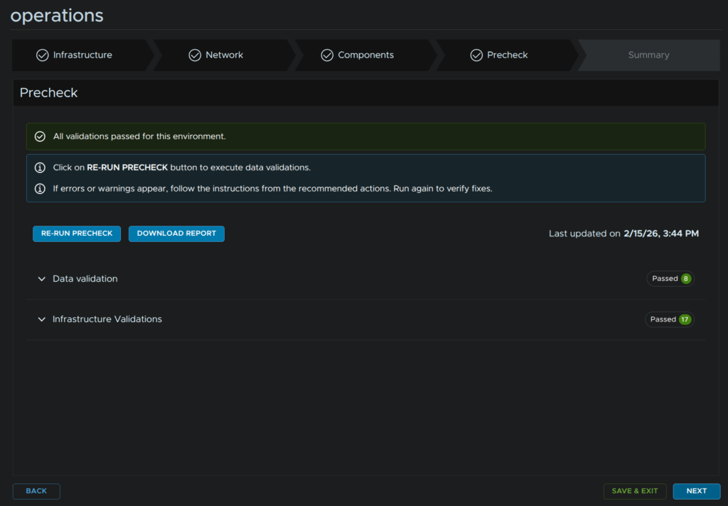
Review the config and click Submit
11.11 – Setting Up The Workload Domain Integration
By Default, the workload domain should get integrated after about an hour or so, but lets properly configure this with our new collector and Ops For Logs
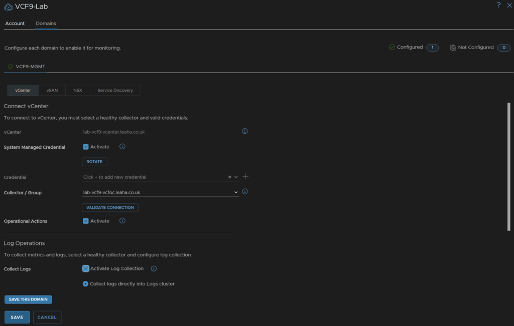
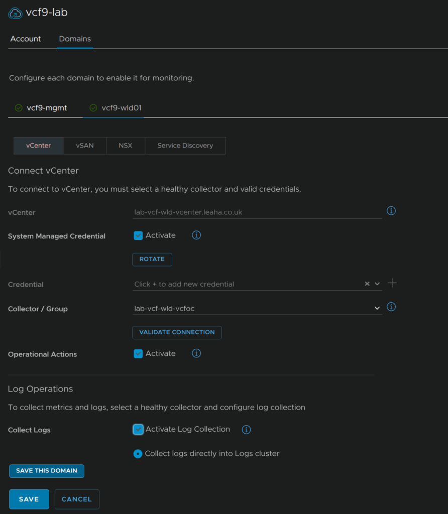
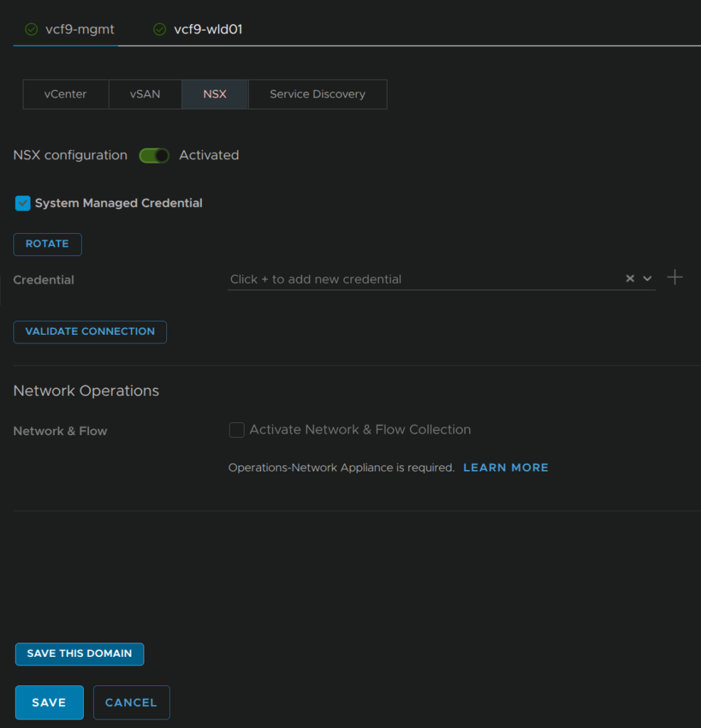
In VCF Operations click Administrator/Integrations, expand VMware Cloud Foundation, then click the three dots on your VCF Instance and click Edit
Make sure System Managed Credentials is checked, select our new workload domain collector, and make sure Operational Actions is enabled, then check Activate Log Collection and click the vSAN tab
Ensure its enabled and SMART data is being collected then click the NSX tab
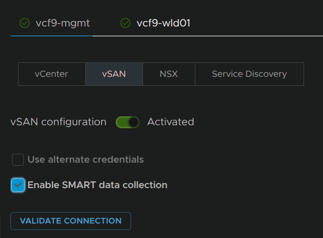
Ensure NSX is activated, if you have Operations For Networks, also enable that, I didnt redeploy it when I rebuilt my lab, so I left it, then click Save in the bottom left
12 – Expanding A Cluster
While this can be done in vCenter, by default this only works on the management domain, for workload domains, VCF SSO and vCenter linking are required, as this is out of scope for this guide, and not all users will have this, I will be using the SDDC Manager UI, while it is deprecated, when it is fully removed, this correct workflow in vSphere should be sorted
Before we begin here we need to ensure we have a network pool, if you are expanding a cluster you can use the network pool already associated with it, if you are deploying a new cluster you can use the existing network pool or create a new one, so you likely dont need a new one, but you must have one you can use, more info is in section 9.1
Available new hosts must be in the inventory from section 9.2
We also need to have an image imported into the SDDC like in section 10
We need to log into the SDDC Manager UI on
https://fqdn
We will then get redirected to login with the management domain vSphere SSO accounts
Click Inventory/Workload Domains and select the workload domain which is having its cluster expanded, I will be doing this on the vcf9-wld01 domain
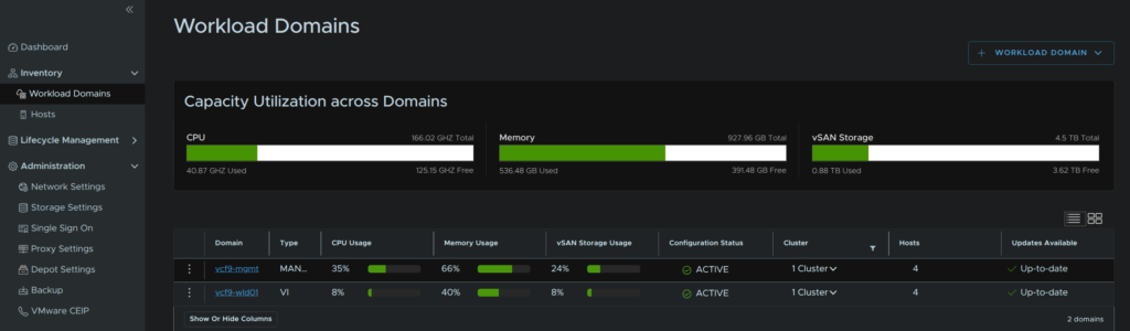
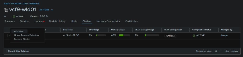
Click the Clusters tab, click the three dots on the cluster and click Add Host
Hosts will need to be compatible with the same principle storage as existing hosts, in my case vSAN, and have the same NIC configuration
Select any hosts to be added and click Next
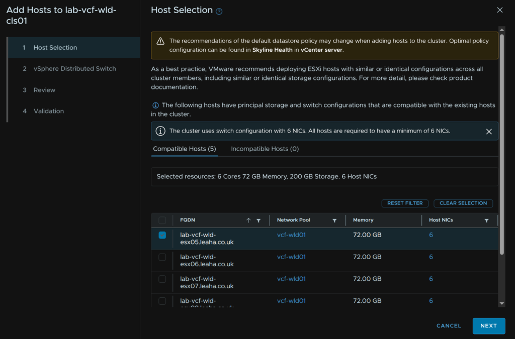
We then need to choose uplinks for the cluster VDS
When you are happy, click Next
Click Next
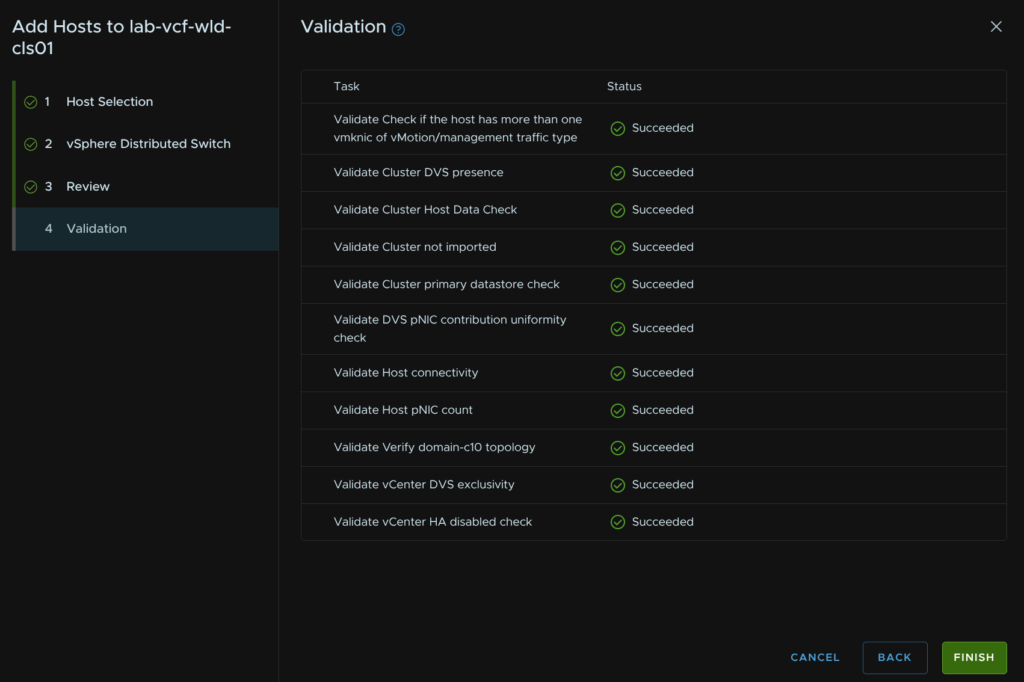
Wait for the validation to succeed and click Finish, if you have errors they will need addressing
13 – Creating A New Cluster
While this can be done in vCenter, by default this only works on the management domain, for workload domains, VCF SSO and vCenter linking are required, as this is out of scope for this guide, and not all users will have this, I will be using the SDDC Manager UI, while it is deprecated, when it is fully removed, this correct workflow in vSphere should be sorted
Before we begin here we need to ensure we have a network pool, if you are expanding a cluster you can use the network pool already associated with it, if you are deploying a nnew cluster you can use the existing network pool or create a new one, so you likely dont need a new one, but you must have one you can use, more info is in section 9.1
Available new hosts must be in the inventory from section 9.2
We also need to have an image imported into the SDDC like in section 10
13.1 – Starting The Workflow
We need to log into the SDDC Manager UI on
https://fqdn
We will then get redirected to login with the management domain vSphere SSO accounts
Click Inventory/Workload Domains and select the workload domain which is having its cluster expanded, I will be doing this on the vcf9-wld01 domain

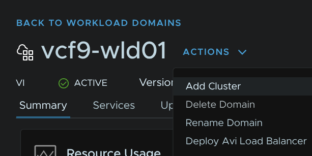
Click Actions/Add Cluster
13.2 – Selecting Storage
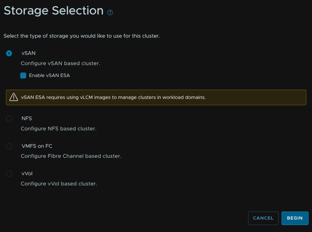
Select our storage topology, in my case this is vSAN, then click Begin
13.3 – General
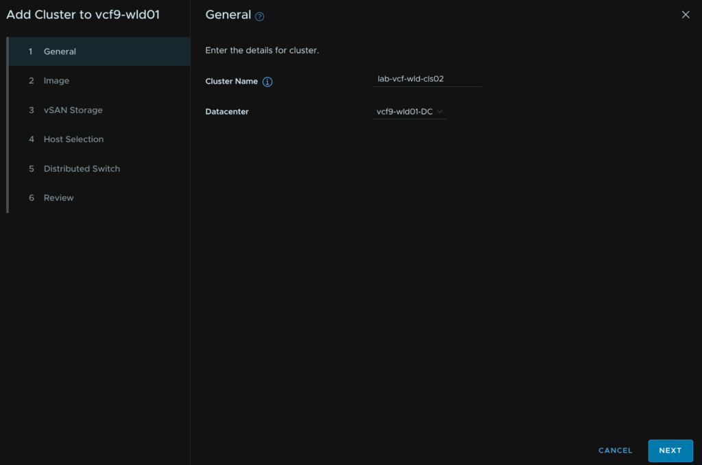
Enter a cluster name, and select the existing datacenter then click Next
13.4 – Image
Select our image, I will be using the same as my first workload domain cluster, then click Next
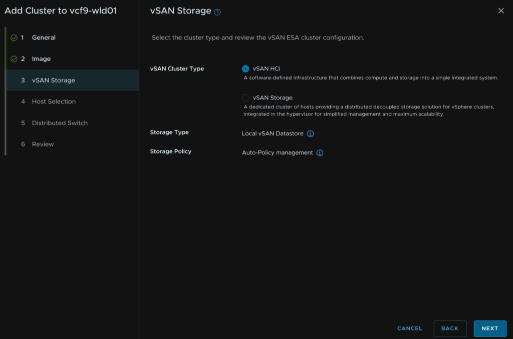
13.5 – vSAN Storage
If you didnt select vSAN storage you will not have this option so skip ahead
For vSAN select the vSAN type, this will typically be vSAN HCI unless you know you need a vSAN storage/Compute cluster, then click Next
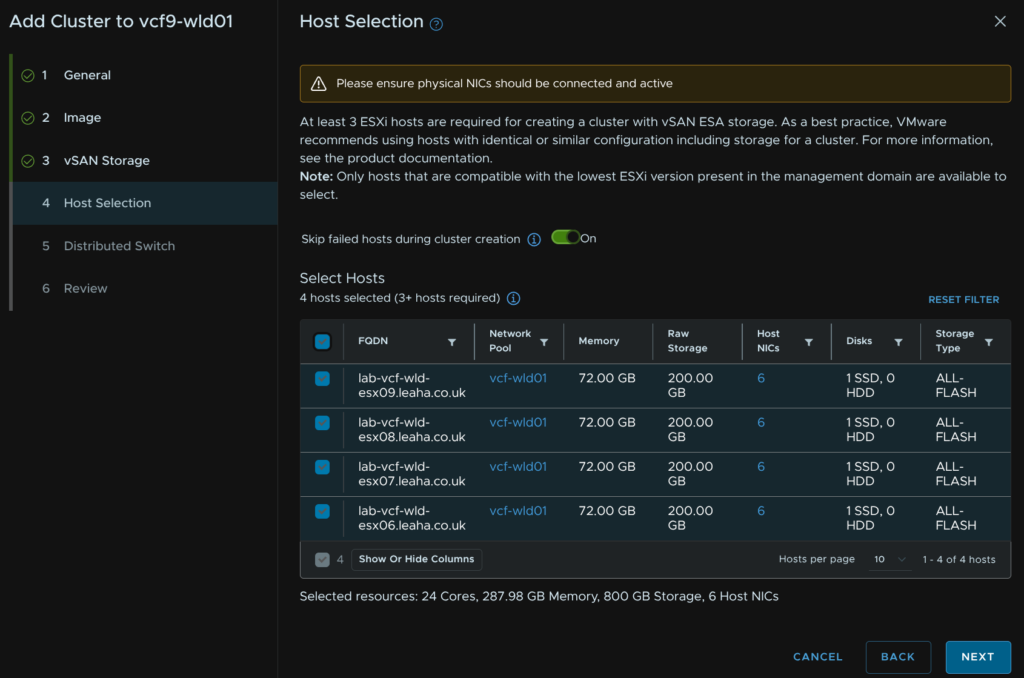
13.6 – Host Selection
Select our hosts and click Next
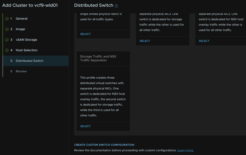
13.7 – Distributed Switches
We will be opting for a 6 NIC config and we want to be manually specifying a topology else we cant set an IP pool for NSX, 4 NICs will also work, just ensure storage is on its own VDS
Click Create Custom Switch Configuration
Click Create Distributed Switch

Add a VDS name and set the MTU, this should be 9000, but in line with what was set for the management domain, we need 2 uplinks, select the vmnics you want to use then click Configure Network Traffic Type/Management
One of these uplinks should be bound to the vSwitch on the default ESX install
Give the port group a name and select the load balancing policy of route based on physical NIC load then click Save Configuration
Click Configure Network Traffic/vMotion
Give the port group a name and select the load balancing policy of route based on physical NIC load then click Save Configuration
Scroll to the bottom and click Create Distributed Switch
Click Create Distributed Switch
Give the VDS a name, set the MTU the same, which should be 9000, select the two uplinks you want to bind for storage and click Configure Network Traffic/vSAN
If you chose NFS configure that here
Give the port group a name and set the same load balancing option then click Save Configuration
Then scroll to the bottom and click Create Distributed Switch
Click Create Distributed Switch one last time
Give the VDS a name, set the MTU to the same, at 9000, then add the remaining uplinks, then click Configure Network Traffic/NSX
Leave the default boxes checked, all three should be, give the overlay transport zone a name, add the host TEP VLAN as the Transport VLAN, set the IP Allocation to Static IP Pool and we can create a new pool or reuse the pool for the first workload domain cluster, I am re using the pool
Select the VLAN transport zone from the drop down and set the NSX uplinks to match the VDS uplinks
Give the NSX uplink profile a name and set the Teaming Policy to Load Balance Source and click Save Configuration
Scroll down and click Create Distributed Switch
Then click Next
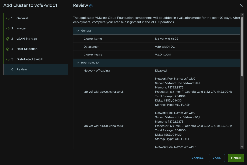
Review the config and click Finish
14 – Fleet Scaling
14.1 – VCF Operations
14.1.1 – Scale Up
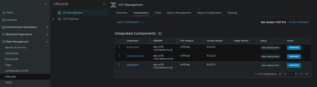
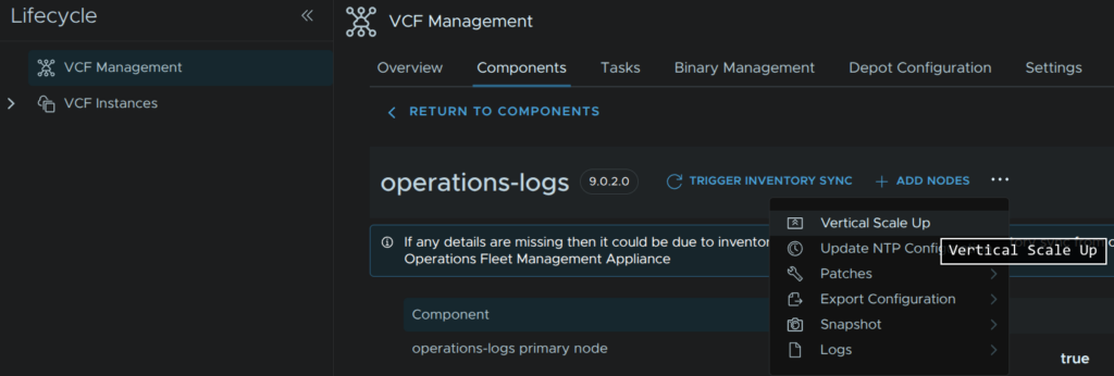
To scale up Operations, log into VCF Operations and click Fleet Management/Lifecycle/VCF Management/Components and click the operations component
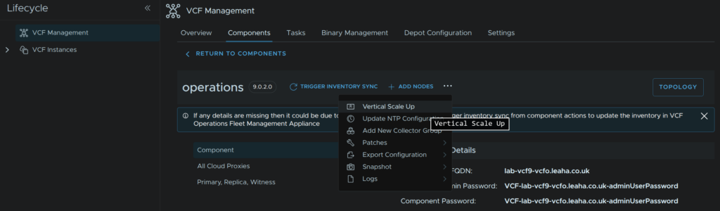
Click the three dots then click Vertical Scale Up
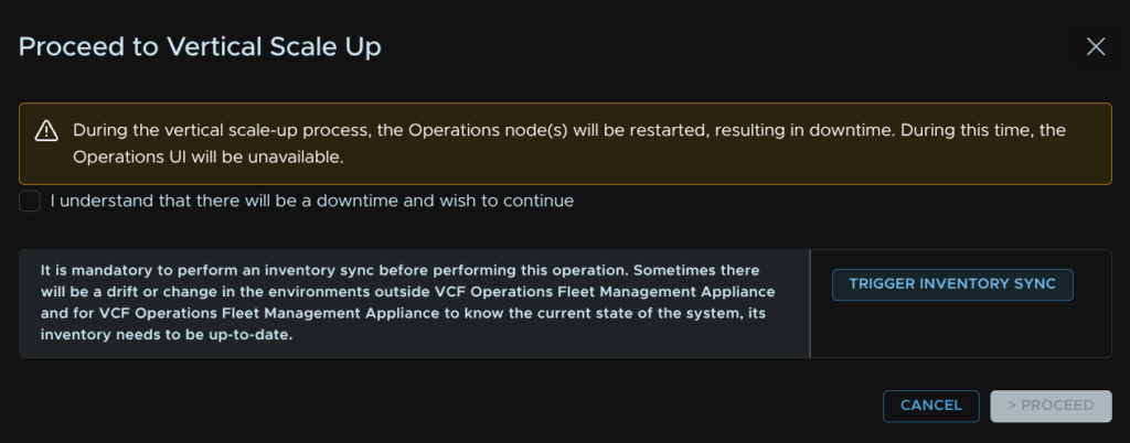
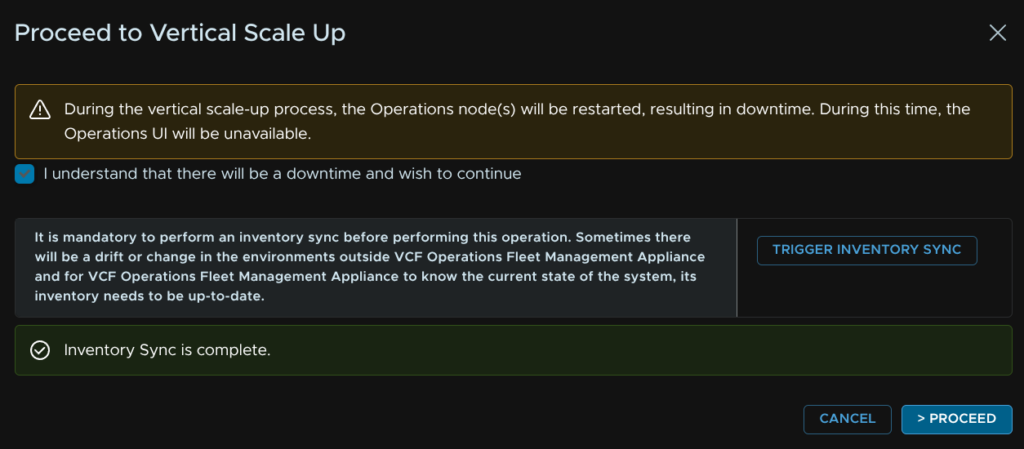
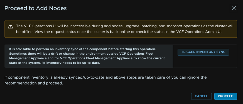
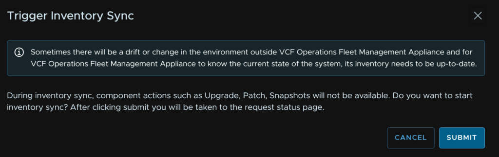
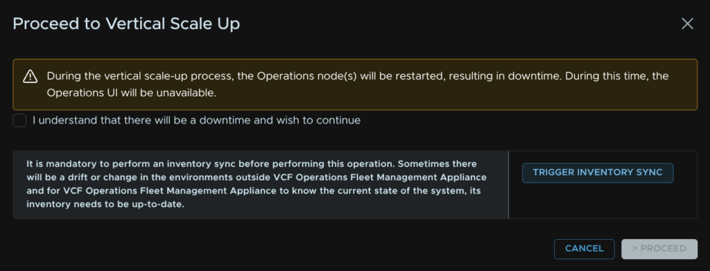
Click Trigger Inventory Sync
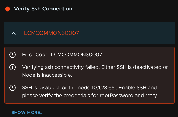
If you get any errors, this is likely due to additional cloud proxes having SSH enabled, to fix that, log in as root on the console and run
systemctl start sshdIf you want it enabled on boot, like the management domain cloud proxy, run
systemctl enable sshdThen re run the inventory sync
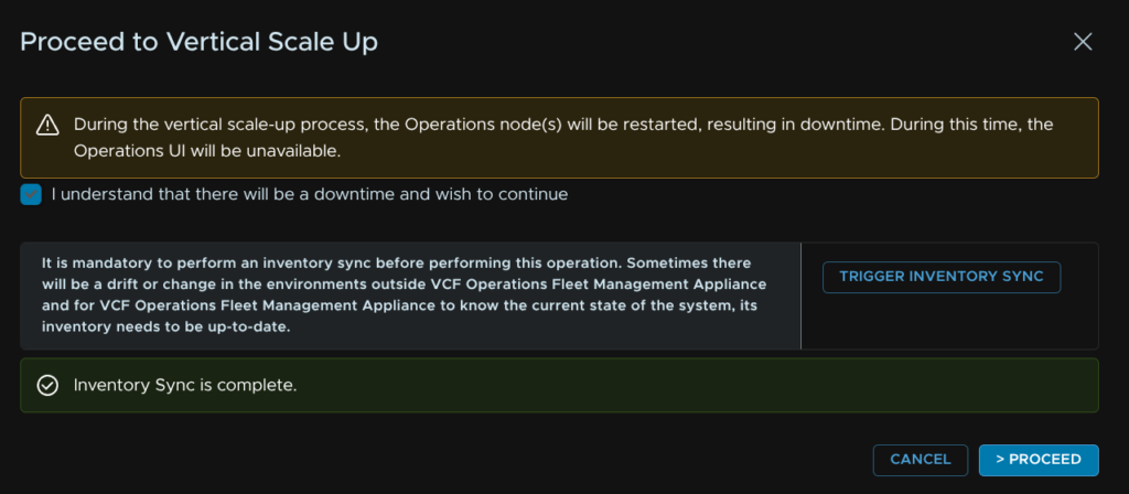
When thats done, check the box to acknowledge this will cause Operations to restart and click Proceed
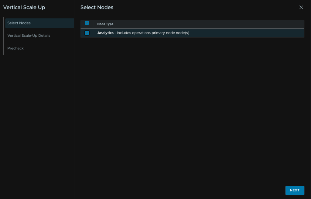
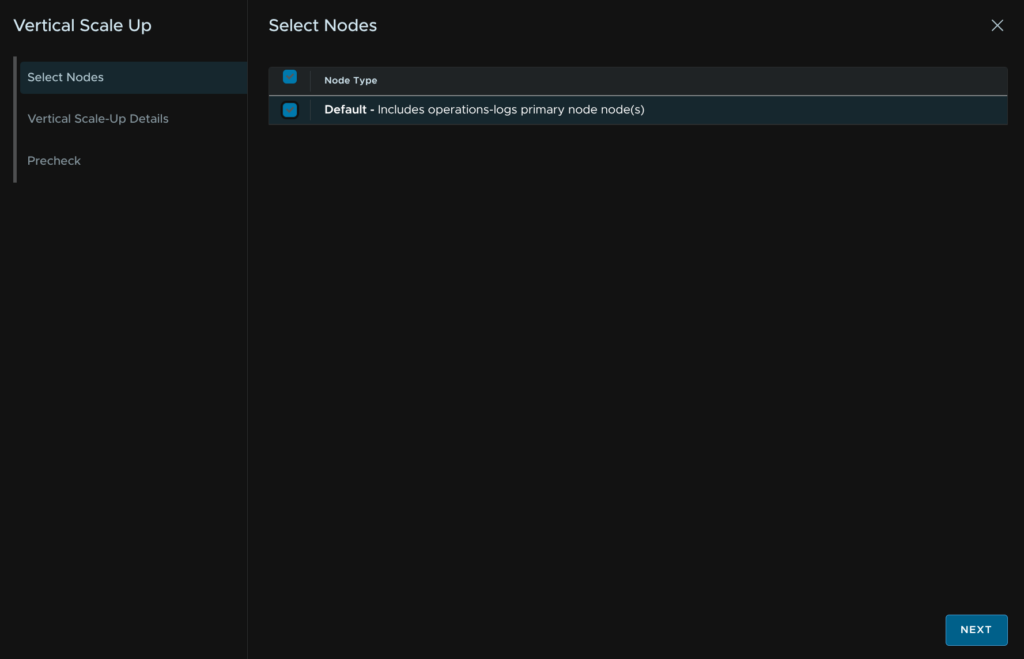
Select the node, as I have a single node cluster thats all I can select, then click Next
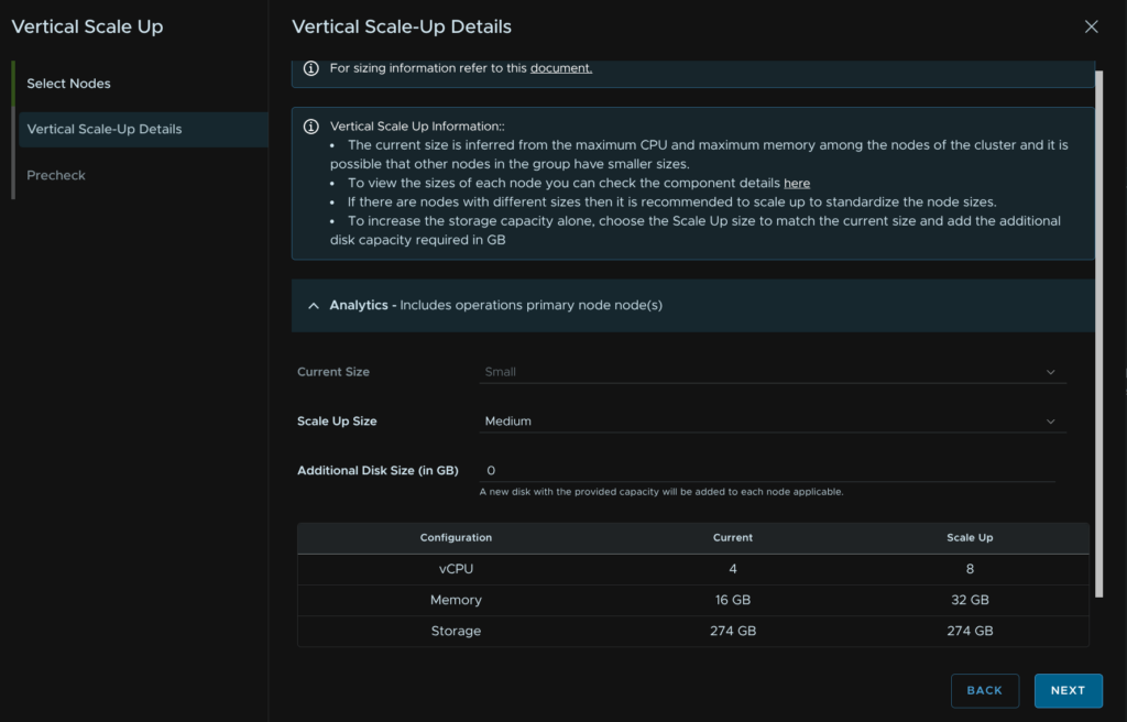
Select the target size, in this case medium, which is really the ideal size, you should scale out before scaling up at Medium, then click Next
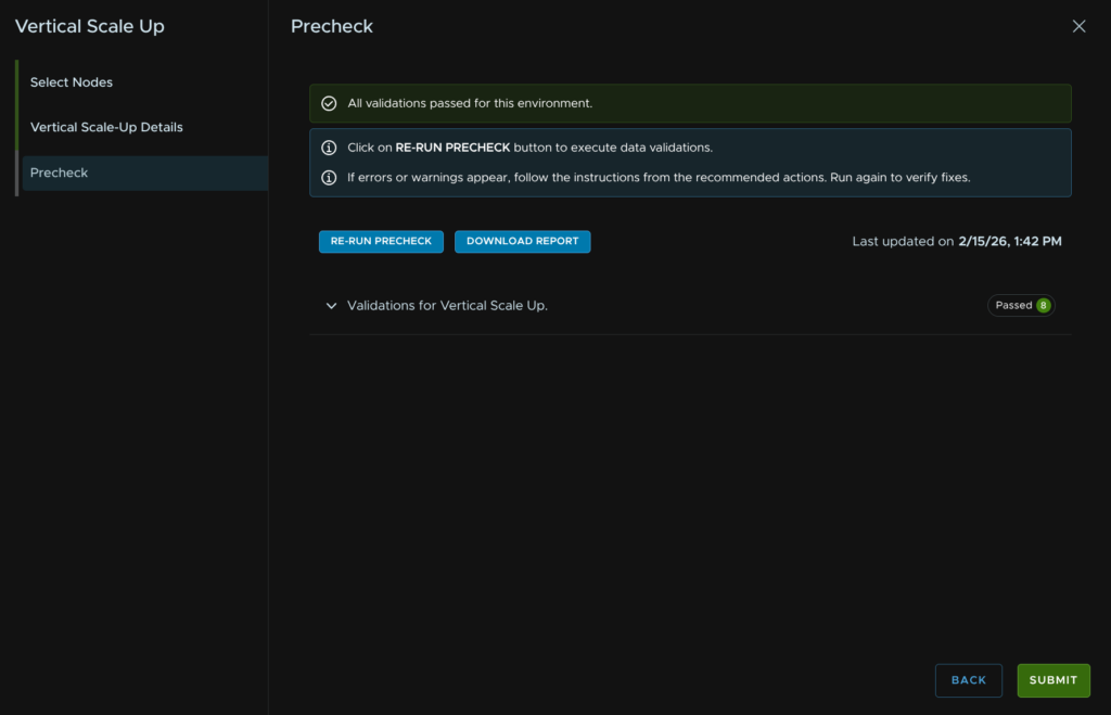
Then click Run Precheck
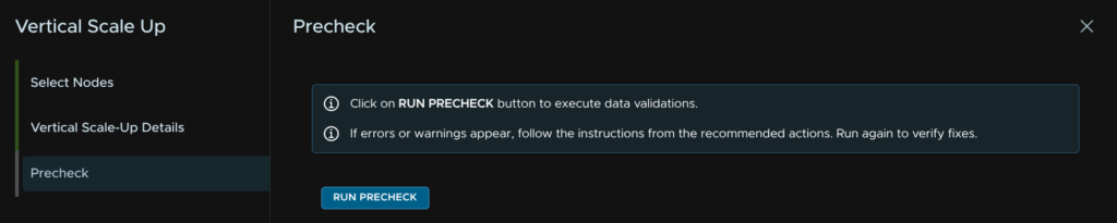
When thats passed click Submit
14.1.2 – Scale Out
Before we scale out, we need to plan what this will look like, in VCF Operations, there are two types of nodes we can add to a cluster
A replica node, this is a copy of the primary node and functions to give the cluster better availability
A Data node, the expands capacity of our cluster and the number of metrics it can take
When expanding from a single node setup to HA, we will be adding one of each for more capacity and availability, if you already have a cluster and need more capacity, you can add just a data node
We first need to ensure we have the VCF Operations Binary matching the current version you are running, in my case 9.0.2, I have this from the installer, but if you dont select the binary and click Download
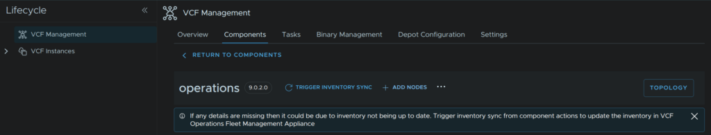
To scale out Operations, click Components and click the operations component

Click Add Nodes

Click Trigger Inventory Sync
Click Submit
When thats done click back to the Components view
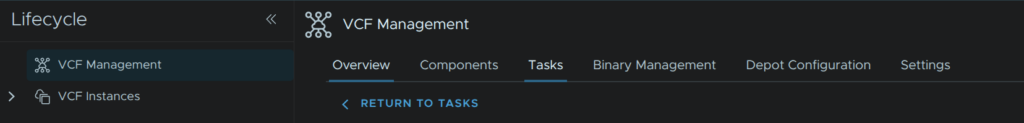
Click the operations component again

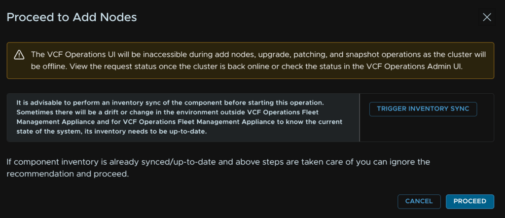
Then click Add Nodes
Now click Proceed
This should all be pre populated, click Next

Click Next again, this should all populated again

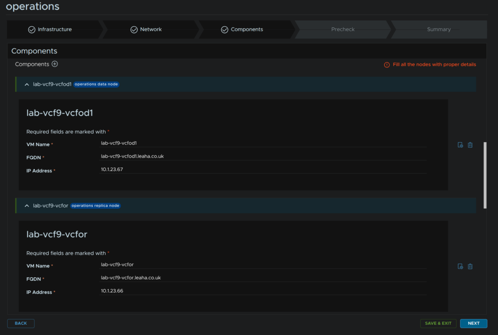
Scroll down to Components, click the + and click Operations Replica Node
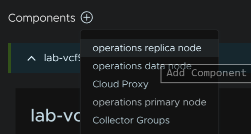
Repeat and click Operations Data Node
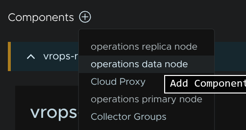
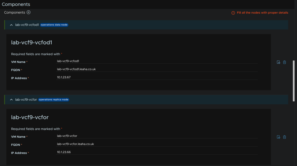
Fill in the VM name, FQDN and IP addresses for the appliances, then click the settings icon, to the left of the trash can icon, on the right
Scroll down to Root Password and click Select Root Password
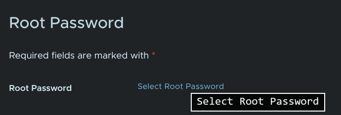
There will be an entry for the VCF Operations root password from the initial deployment, use this to keep things a little more simple, you can add a password if you close this menu down and scroll up, if you need

Then click Save
Repeat for our other node, then click Next
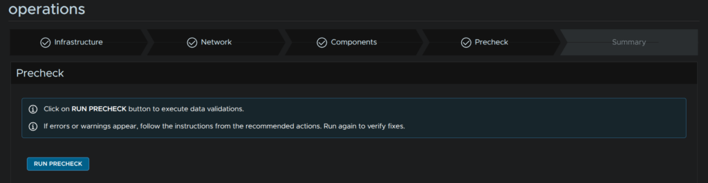
Click Run Precheck
When thats passed, click Next
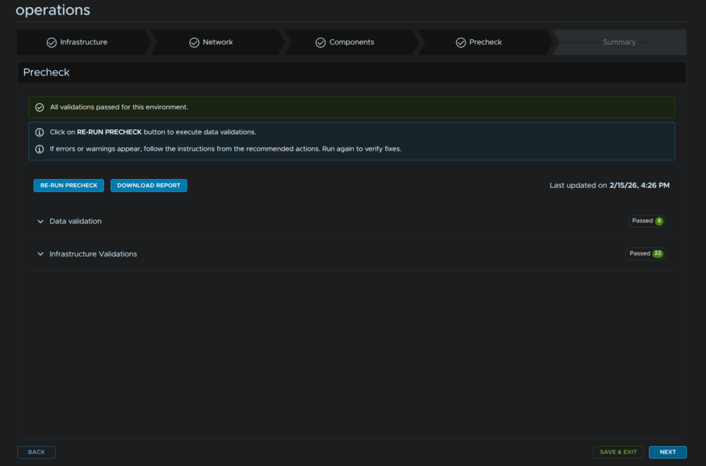
Then review the config and click Submit
14.2 – VCF Automation
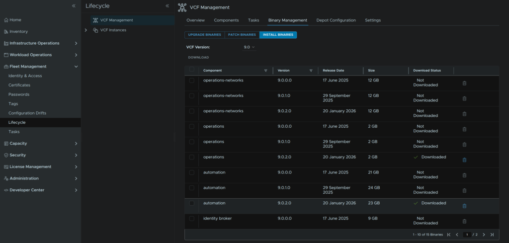
Automation can only be scaled out into a cluster, we first need to ensure we have the VCF Automation Binary matching the current version you are running, in my case 9.0.2, select the binary and click Download
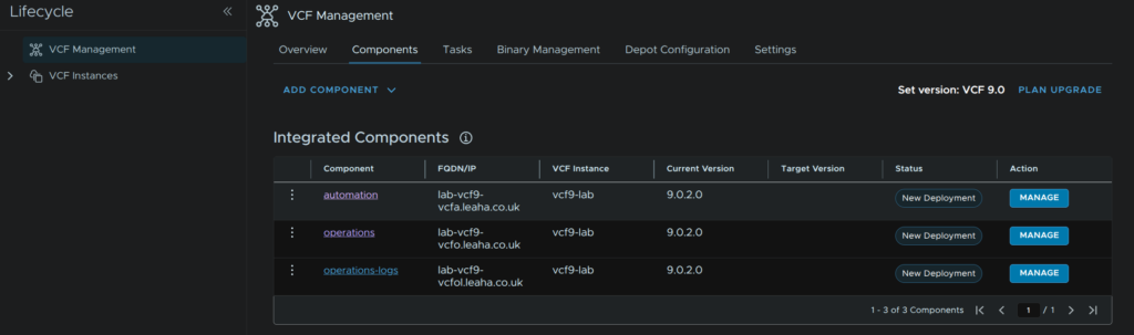
To scale out Operations, click Components and click the automation component
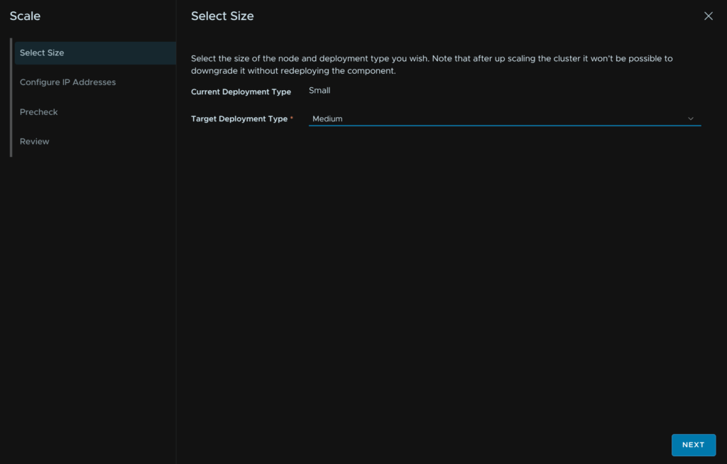
Then click the three dots and click Scale
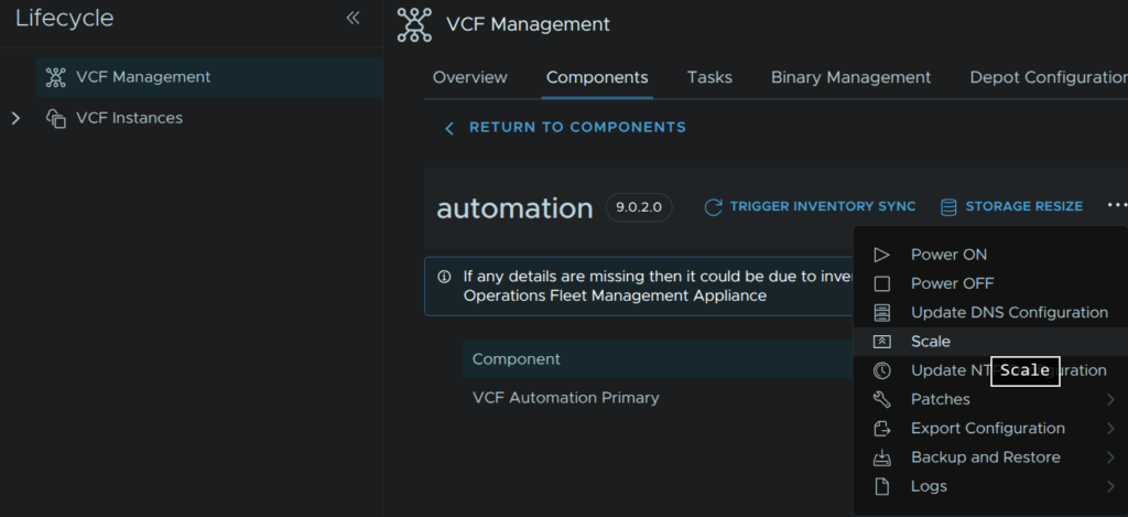
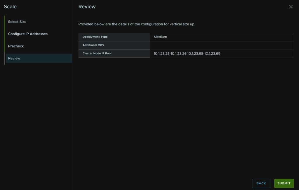
Select a target size of Medium, Large is basically same config, then click Next
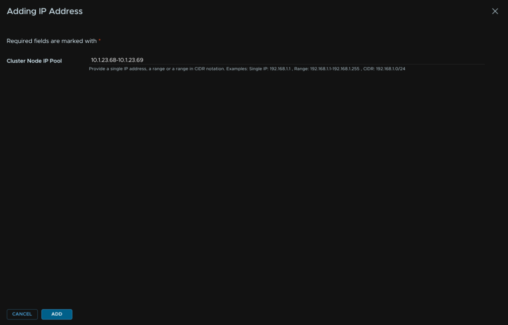
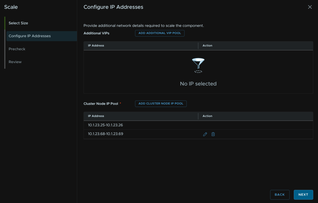
The default single node setup will have two IP addresses in a pool, we need a total of four IPs for a HA cluster, click Add Cluster Node IP Pool
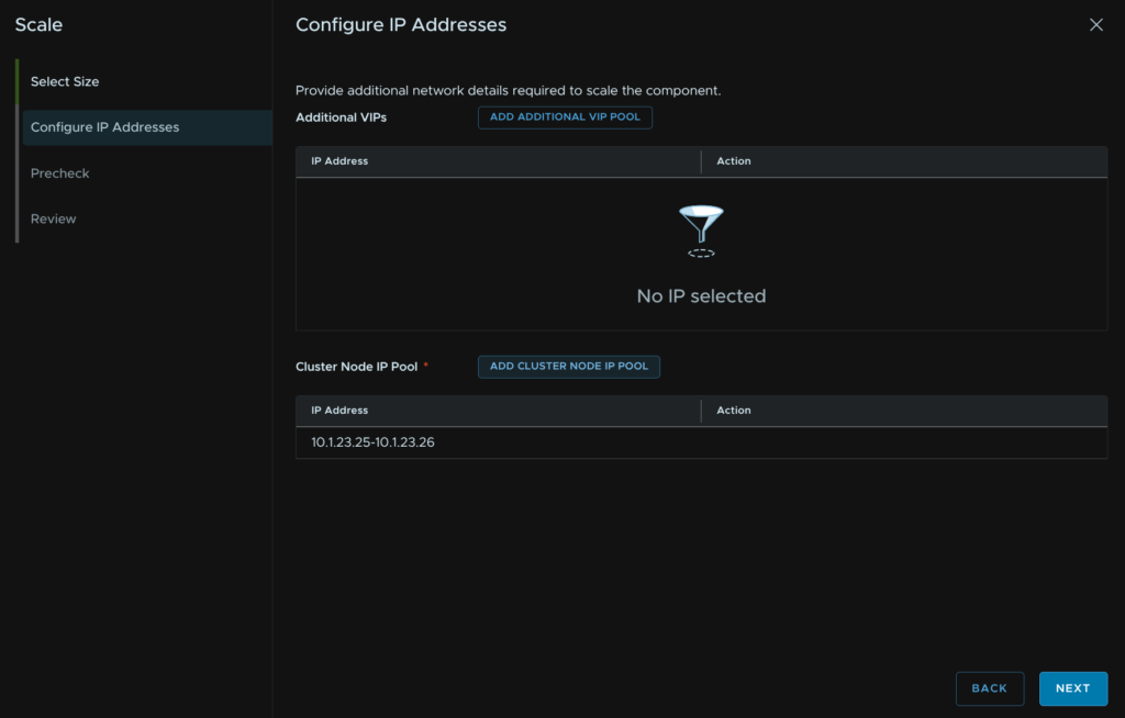
Enter a range of two IPs on the same subnet as Automation and click Add
Then click Next
Click Run Precheck
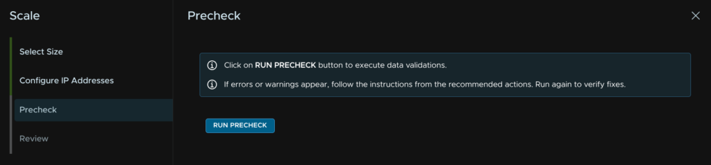
Then click Next
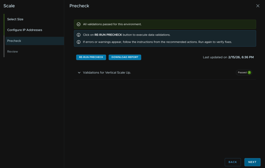
And click Submit
14.3 – VCF Operations For Logs
14.3.1 – Scale Up
For Operations For Logs, we can scale up compute and/or storage, if you need more log space here is how you add more disks, in a multi cluster setup ensure all nodes have the same disk capacity up to 4TB
To scale up Operations, log into VCF Operations and click Fleet Management/Lifecycle/VCF Management/Components and click the operations-logs component
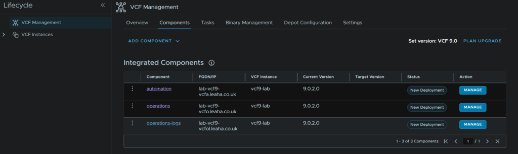
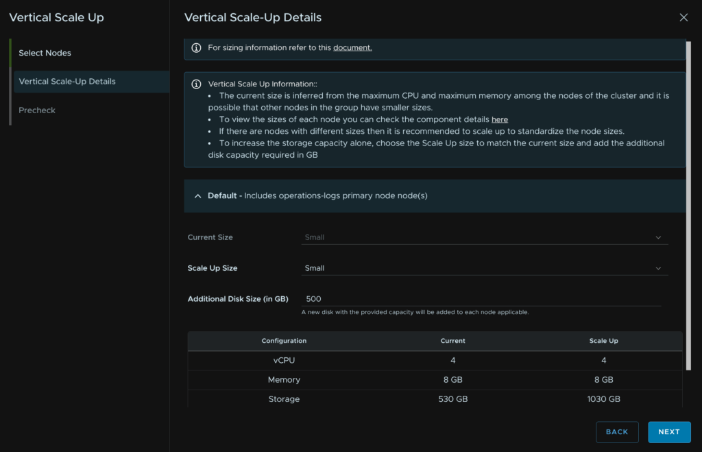
Click the three dots then click Vertical Scale Up
Click Trigger Inventory Sync
When thats run check the box to understand downtime will occur and click Proceed
Select the node and click Next
Input the scale size for the node if you are increasing the compute, in my case I am adding more disk, then click Next
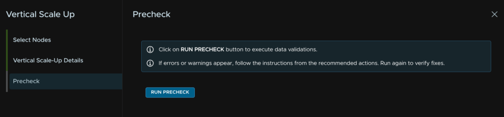
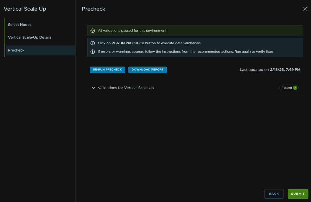
Then click Run Precheck
When thats passed, click Next
How is doing the Aria automation the discovery for supervisor service ? via management interface of the supervisor or other way ?
VCF Automation just picks up the supervisor as its connected to the SDDC Instance, you dont need to do anything
How long will it take from start to finish for first timer
This depends on so much its too hard to say
The size and scale of the environment, the amount of post deployment configuration, and your overall skill/ability with the product influence the time massively
Is there your email address where i can communicate if you dont mind
My email is at the bottom of any page, though I have seen you put 4 comments today, I dont mind answering some questions in the comments, but its definitely not a help service
Excellent guide, though ‘flowcontrol receive on’ is an interesting choice. I probably would not recommend this.
This was the switch default, these also are some interesting kinda non standard switches, so that may be why its on, they are FN410S models, they were based on, in the FX2S chassis
Sr, i dont see Workload Domain in guide?
Adding additional workload domains, hosts and clusters are on my to do list and will be coming at some point, sorry they arent available at the moment
Nicely written, I have went through many guides and this seems to be a very good one.
However, I am struggling with one issue each time during deployment with “Failed to Add Hosts to VDS”.
Could you please show me Portgroups attached to the NICs of each ESXi host.
Also, as mentioned on your guide you have 6 NICs, did you configured anything within the vSwitch/VMK/PG of ESXi host.
There is a section on the VDS port group migration that might help, is this a nested virtual setup? This error always happens on those environments, with physical hosts you should be fine
Really complete and accurate document! Just on note, when you configure the Workload Domain Connectivity, only the VPC external IP block must be unique, not overlapping in the datacenter fabric, while the private – TGW IP blocks can overlap, since these addresses will be natted.
Yes, they will be, but if they overlap with existing IPs, this will cause a routing error when you walk the packet and if they exist in the physical datacenter, workloads behind the transit gateway will never route to them
Can you please put the networking ( vlan – portgroup creation and nic requirement etc ) in the pre-req creation section so it will become complete guide for nested setup
The pre requisites covers the networking requirements already and all my VLANs used in this, so I am not 100% what you are asking for
Port groups are in the VCF Installer section for the relevant part of the installer
A nice step by step guide for sure.
Being newbee in IT, it would be great to see a virtual router configuration guide for this setup; so we can try entire thing in homelab.
Thanks
Raman
I’ll see if I can add some bits, I used OPNsense for my lab, so I did end up excluding the configuration as businesses typically are doing their routing/BGP on Core/ToR switches
But that is something I can look at, appreciate its a little older of an article and doesnt fit 1:1 with this guide, but my NSX lab deployment back from November 2023 did include the OPNsense side for BGP in section 5.4 and section 1 covers a lot more OPNsense config, if this is of any help – https://blog.leaha.co.uk/2023/11/12/deploying-an-nsx-lab/
Hi,this is a fantastic article. Since I am currently preparing some experimental materials, may I ask if you could provide a Word document version of the blog content?
Hi, I cant unfortunately, plus the information is accessible online to anyone already, why exactly do you need this in a word document?
Please note, this may not be copied and used in business documents without permission
Hello, good day. Your guide is very good, thank you, but I have a question: if I now want to add VFC Operation in high availability, how should I do it? What would be the best practice for applying it?
Look through the fleet scaling section, this covers expanding Ops into a HA setup, continuous availability not covered, alternatively you have a HA setup during the deployment, but that puts everything into HA
Thank you very much, I was able to install another replica and data component for the operation.
Hi, we have environment, in which I have 3 physical esxi connected to the physical cisco switch, in which int vlans are configured with ip (172.20.10.0/24) which has internet access. Those 3 physical esxi are managed by the vcenter, in which 9 nested esx are deployed and inside the nested esxs only, we are deploying the VCF. I have created portgroups on the VDS of vcenter with the vlan id 2010, and when I give vlan 2010 in the VCF wizard too, it is getting double tagged, If I make the portgroup on the VDS as trunk, the nested esxs goes down. Can you provide suggestions on how to resolve this?
If you are doing this, for VLAN 2010, the way I do it is to have the ports on the physical switch trunk VLANs down to the physical hosts
Put the nested hosts on a trunk port group, you will need to enable mac learning, forged transmits etc, all those setting else nested labs can have connectivity issues
Then assign the VLAN to the network on ESX in the installer/where ever needed
Have you tried all of that?
Yeah, I have tried connecting the nested Esx to the trunk portgroup and then assigning vlan 2010 to the esx via DCUI, but then, connectivity of the nested esxs are going down, couldn’t reach the gateway present in the physical switch.
That sounds like something with the phyiscal networking
VLANs should be trunked no, no native VLAN set that overlaps with the lab VLANs
All I know is that will work, some it sounds like something else is up unfortunately
Thank you for your guidance, will check with the networking.
Hey, I have resolved the issue, thanks for guiding. At first when I created a trunk portgroup in the vCenter with the type of Vlan as VLAN trunking with range 4095, the traffic didn’t flow. Now I kept the range of the trunk portgroup as 2008-2011 then it worked.
This is really a great documentation.
We had a “SomeBranded” hci cluster, 4 nodes (vmware v8u2 / not vsan). I was able to build a simple deployment on 3 nested ESXi using VCF 9.0.0 (Thanks to You and WL blogs) from this HCI cluster.
Now we deleted the “SomeBranded” hci deployment, total wipe out. Since the HW passed the HCL, we went to deploy a VCF9 (HA), and successfully done it (no Day2 config yet). But this will serve as a Demo for our customer, and I won’t really be able to repeat the deployment process to it, and play around with the configurations. this is for my preparation taking the certification.
Now I created Nested ESXi again over it, and tried the same procedure, but I cannot get passed the NSX deployment. I tried tweaking the Wait/Time-out as per WL etc. Tried also 9.0.0 and 9.0.2, but I’m not getting past NSX. if I look at the NSX appliances, some services are not able to start (integrity-checker, LSB, etc.) and VCF installer keeps on trying to delete and redeploy these and getting stuck in there.
What is the error you get at the NSX part?
Cant say I have seen anything like that with the services though sadly, there may be something in the SDDC manager logs, with the SOS tool
Hi Thanks for getting back. however, I deleted my vms already after numerous tries.
What I did now is create a new VM (I chose compatibilty 8u2 instead of 9) – just guessing because previously, what is installed is v8u2.
and voila, i was able to finish deploying VCF9 (but only in simple mode and no automation for now) because on my first few try (HA and with Automation) it was failing around the Automation deployment, so I chose simple with no automation for now. I will try to add it later. I’ll continue following your guide for now. Thanks.
Hello,
Just curious can the supervisor control plane be in a separate vLAN then where vCenter/Operations management network runs from?
Thanks!
The Supervisor control plane can be kinda where ever you want it, I used the same VLAN, but it absolutely doesnt have to be, just select a different vSphere network when deploying it, you can even deploy it to VPC subnets if you wanted to
Hello, in this guide we only have 1 instance in the automation, what would be the procedure to add more instances and form an automation cluster?
Leaha, do you happen to have a guide from the previous consultation?
Hi Leaha,
I have a question regarding how to design the physical network for a lab where we can use NSX. I have a home modem provided by an ISP and a Layer 3 switch where I would be configuring the VLANs (this switch does not support BGP or ASN).
Our idea is to connect port #1 of the switch (on the default VLAN 1) to our ISP modem, create the additional VLANs, and route the VLAN traffic through the switch towards the modem.
We have an Aruba J9729A switch, the ISP modem, two ESXi servers, and Fiber Channel (FC) storage.
Do you think this implementation is possible?
If you Juniper can do L3, youre probably best of having some VLAN/Network shared between the Juniper L3 switch and ISP router with a static route to forward internet traffic out, that way the Juniper can handle all the VLANs needed for VCF, like it works in a datacenter where the core does the routing and outbound/firewalled traffic is sent up to the firewall then externally to the router
So I think that should work
Its also worth checking out the VCF 9.1 guide too as thats new and probably a little more worth looking at 🙂
Hi Leaha,
excellent guide, thank you for sharing.
In case a customer purchased VCF licences but they just need to deploy a basic vSphere environnement ( vCenter, couple of hosts and SAN storage) do we still need to go through the same steps ? is deploying NSX mandatory ? I read somewhere that using vSAN storage as primary for deployment isn’t mandatory anymore, would you please confirm ?
thank you
It depends what you want
Do you want all the features, you need a chunk of it, VCFA is optional
The bare minimum is VCF Ops and the license server plus vSphere, as all licensing is handled via Ops, plus, regardless of environment size it brings SO much to the table its really a requirement for managing everything efficiently vs vSphere